This thread has been locked.

If you have a related question, please click the "Ask a related question" button in the top right corner. The newly created question will be automatically linked to this question.

AFE20408: DAC output method and setting

Part Number: AFE20408

Hello,

My customer informed that they cannot see the DAC output. They are using AFE20408EVM. Please help to solve this problem.

The customer's register setting information is as below.
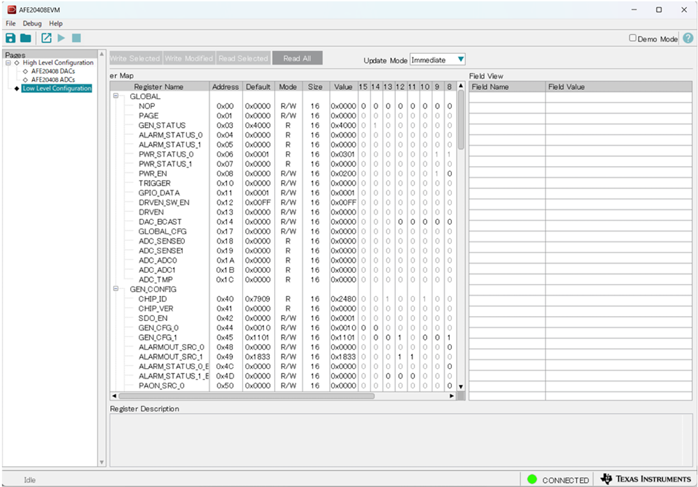
image.png


image.png

I translated the following E2E information into Japanese and sent it to the customer to configure according to this content, but they cannot confirm the DAC output.

https://e2e.ti.com/support/data-converters-group/data-converters/f/data-converters-forum/1407117/afe20408-getting-started-guide-request?tisearch=e2e-sitesearch&keymatch=AFE20408#

Is there any missing or mistake in the customer’s register settings or a different procedure?  Please let us know the correct register setting contents and procedure.

There is also a request about documentation on how to configure registers in the GUI in more detail than what is documented in the AFE20408 Evaluation Module User's Guide. If you have such materials, please provide them.

Thank you,

T.Imai

  • Hi T.Imai,

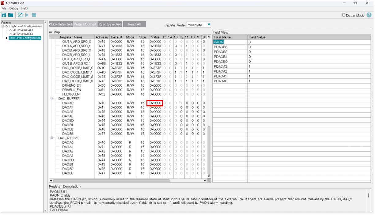
    Based on the photo you sent, it looks like they did not write any data to the DAC. They should write the ideal DAC value into the "DAC_BUFFER" box. 

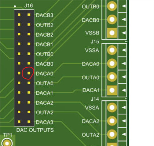
    Once they set this register, measure the voltage on the circled pin.

    The EVM GUI is meant to be used in tandem with the data sheet. The "Low Level Page" shows the entire register map of the device. You can double click the "value" box of a specific register to write your hex data into it. The below picture shows how that would look like. You can also read the current value of a register by selecting the register and clicking the "Read Selected" button at the top.

    Thanks,
    Erin

  • Hi Eric-san,

    Thank you for your support.

    The guidance you provided is easy to understand and I think customer can check the DAC output with it.

    I will inform it to the customer and ask them to confirm the DAC output.

    Customers have requested detailed documentation on how to configure the AFE20408 using the GUI that is easy for beginners to understand.

    Don't you have anything like that?

    Best Regards,

    T.Imai

  • Hi Eric-san,

    I received the following reply from the customer.
    ・The value of DACAx_BUFFER has changed in the past, but the output pin voltage has not changed.
    ・I confirmed that the register value is also the set value.
    ・Below is the GUI screen captured. Please check if there are any omissions or mistakes in the settings.  DACA0_BUFFER is 0x1000.

    ・I pressed the Read Selected button and verified that DACA0 is 0x1000 asbelow. However, the voltage on the DACA0 output pin did not change.

    I have simlar question about ADC setting.

    Even if I pressed READ with the following settings, the ADC reading is unresposive.

    However, the ADC value could be read by pressing READ after setting ADC_Trigger as follows.


    Can you tell me if ADC settings can be read only after setting ADC_Trigger or if this is the right way?

    I don't know from the datasheet or the EVM user guide whether this is the right way to read ADC values.

    I can see the Low Level Configuration is D13 as below.

    The customer wants the detailed documentation on how to configure the AFE20408 using the GUI that is easy for beginners to understand.

    If you have such one, Pleasse share it with us.

    Thank you,

    T.Imai

  • Hi T.Imai,

    We do not have any additional documentation.

    For the ADC:
    The customer must first select "Trigger ADC" to start the ADC conversions. This is specified in the datasheet. Once the ADC is converting, you select the "READ" button to grab data from the ADC registers.

    For the DAC:
    I'm still suspecting that they are not measuring the correct test points. Please have them read the following registers:
    -GEN_STATUS
    -PWR_STATUS_0
    -PWR_STATUS_1
    -DACA0 in the DAC_ACTIVE section

    These will help me determine if there are any errors preventing DAC output.

    If not, please ensure the customer is probing one of these locations. If the customer is probing the pin to the right of DACA0 circle, they will measure 0V. By default, all DACs start up in the negative voltage range, so measuring 0V means they are not actually measuring the DAC.

    Thanks,
    Erin

  • Hi Eric-san,

    Thank you very much for your support.

    I got information fro the customer that they could see the DACAx output voltage by changing the DACAx_BUFFER registor.

    That was happened after they supplied -5V to both VSSA and VSSB.

    However, there is another question about DAC 13bit resoolution. I would close this subject here and open the new E2E for DAC resolution.

    Thanks and Regards,

    T.Imai