


Part Number: ADS1198
I'm seeing a small issue in the data on our custom PCB and wanted to get your review.
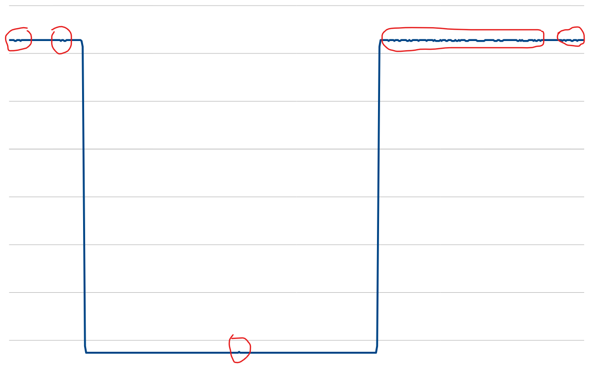
- Raw ADC data occasionally changes by 1 ADC code for a single sample e.g.:
15, 15, 15, 14, 15 - This creates a visible spike or glitch in the calculated voltage and plotted signal.
- The is present in both internal test square wave signal and external input signal with ECG simulator.
Current configuration
- SPI clock: 5 Mbps
- Sampling rate: 500 SPS
- Continuous read mode enabled
- Data is read only after DRDY is asserted
| Register | Internal Test Signal | ECG Signal |
| CONFIG1 | 0x04 | 0x04 |
| CONFIG2 | 0x18 | 0x20 |
| CONFIG3 | 0xCC | 0xCC |
| LOFF | 0xBF | 0xBF |
| CHnSET | 0x65 | 0x60 |
| RLD_SENSP | 0x00 | 0x06 |
| RLD_SENSN | 0x00 | 0x02 |
| LOFF_SENSP | 0xFF | 0xFF |
| LOFF_SENSN | 0x06 | 0x06 |
| LOFF_FLIP | 0x00 | 0x00 |
| CONFIG4 | 0x02 | 0x02 |
| WCT1 | 0x0B | 0x0B |
| WCT2 | 0xD4 | 0xD4 |
Attaching schematics and plots. Also wanted to review decoupling capacitor placements etc.
internal_1.csv internal_2.csv internal_3.csv sim_1.csv sim_3.csv ads1198.pdf
