This thread has been locked.

If you have a related question, please click the "Ask a related question" button in the top right corner. The newly created question will be automatically linked to this question.

ADS131E08: Vcm range calculate check

Part Number: ADS131E08
Other Parts Discussed in Thread: ADS130E08

Hi TIer


Could you help me check the VCM input range of ADS131E08

AVDD = +2.5V , AVSS = 2.5V , VREF = Internal 4V ,PGA =2 

AVDD = +2.5V , AVSS = 2.5V , VREF = Internal 4V ,PGA =4

We calculate the range looks like not correct.

And we test :

When  Vcm = 1.7V , PGA = 2 , output is unnormal.

When  Vcm = 0.96V , PGA = 4, output is good.

We not sure why test result not follow datasheet.

Could you help check . Thank you very much.
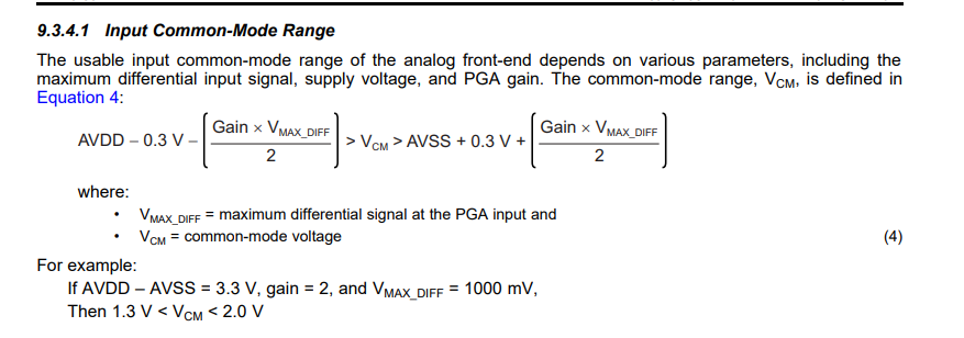
image.png

We calcutlate


  • Hi Tony,

    What's the input voltage when you did both tests? Single-ended or differential input? 

    When the power supplies are ±2.5V, the ideal Vcm is 0V. Is there any reason you wanted and tested Vcm=1.7V?

    Can you please post the customer name in the Notes section of the Thread Tracking Toolkit?

    BR,

    Dale

  • Hi Dale

    This is because the ECG system will need to label the input common mode voltage range in their datasheet. The customer found that the input common mode voltage range of the system was not consistent with the datasheet calculation. Can you help confirm what the correct input common mode range is under current conditions? Input amplitude We can assume that a sine wave of 100mV with a common-mode DC voltage of 1.7 V when differential input and single-end input. 

  • Hi Tony,

    The Vcm range depends on the power supplies, Gain and maximum differential signal (VMAX_Diff) that is is defined as the maximum magnitude of the differential input signal that appears at the PGA input. Below are two examples for VMAX_Diff =500mV and 100mV according to the equation (4) in the datasheet.


    Can you please post the customer name in the Notes section of the Thread Tracking Toolkit?

    BR,

    Dale

  • Hi Dale

    I send the customer name in note.

    We have also calculated it in a table 

    The customer said that the system was operating correctly when measured, but the theoretical calculation of VCM exceeded the system limit VCM_MAX. 

    Can I understand that when VCM exceeds the maximum, the system will work but performance will drop? What happens after exceeded VCM_max or min? 

  • Hi Tony,

    Thanks for sharing the information.

    The description about the common-mode voltage in ADS131E08 datasheet is not quite clear, what it shows is that the internal PGA has limitations and your input must be within a certain range because the PGA is limited. The PGA is formed like the front end of an instrumentation amplifier. Because of this PGA input is limited by the amplifier range of operation, the limitation can come from the input or output range of the amplifiers. Because the input and output of this PGA must have the same common-mode voltage, the input common-mode is more limited with higher gain. The ADS130E08 is an older datasheet. There is a similar but better explanation in some of our newer datasheets. You can look at the ADS124S08 datasheet in the Low-Noise Programmable Gain Amplifier section and PGA Input-Voltage Requirements section for the details.

    For the conditions in the second test (Gain=4, Vcm=0.48V) you showed above, the output of the PGA is close to hit the allowable rail, you may not see a bad output if your input is a differential DC signal, however you will see a bad result if you are checking AC performance with an AC signal or you are checking linearity performance. 

    For the conditions in the first test (Gain=2, Vcm=1.7V) you mentioned above, the more important thing is to know the voltage applied on the AINP and the AINN pin of the ADC, the result could be different with different voltage on the AINP and the AINN but the same Vcm.

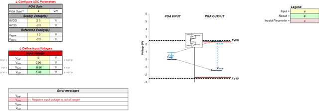
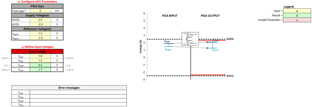
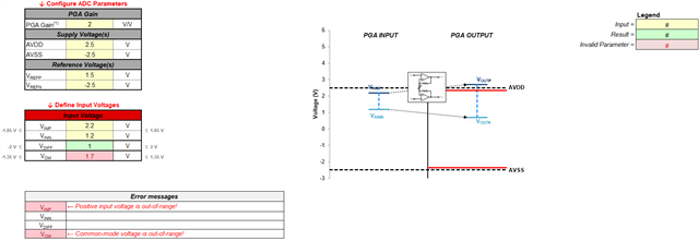
    You may use the following tool as an approach to check, below are three examples with different conditions.

    ADS124S08-EXCEL-CALC-TOOL  ADS1x4S0x Design Calculator

    Example 1:

    Example 2:

    Example 3:

    BR,

    Dale