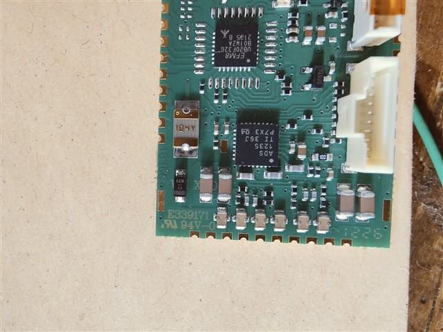
ADS1235: temperature compensation issues

Part Number: ADS1235


I am currently looking to replace an EOL ADC (Cirrus CS5532) with a similar 24-bit device.  We have used many tens of thousands of the CS5532 without tempco issues.  I have developed a replacement prototype (photo above) with the ADS1235 and adapted the SPI code of the EFM8 microcontroller. I have configured 3 of the prototypes and compared them with 3 of the previous CS5532 equipped boards.  One of the prototypes provides excitation volts (4.6v) to my precision load cell simulator external to the temperature chamber.  Sense and signal returns from the simulator are commoned to all 6 modules (but not excitation, of course).  Picture above – the switch is to select the TTL232 serial outputs of the six modules.

The precision simulator provides 0.7mV/V at span and 0 at zero.  I have calibrated all modules to output 10000.0g at 0.7mV/V, 0.0g at 0mV/V.

Setup params - 50sps, DCexc, continuous, sinc3, PGA x64, AIN4/5 signal in, REFP0/REFN0.

OFCAL: 00,00,00h (approx), FSCAL: 8D,F6,80h (typ).

The analogue schematic is attached.

I have used the previous, quite high input and ref series resistors (22k), so when I encountered issues, I reverted to the application note recommended of 100R and 10nF and 1nF caps (C0G).

This made absolutely no difference.

Over the course of a day, with temperatures varying by no more than 5C (22 to 27C), the ADS1235 zero corrected span creeps up and down typically from 10006.4g to 10027.0g (~200ppm), whilst zero moves 0.0g to 3.8g (38ppm).  The weird thing is, all of the ADS1235s seem to track this gain creep.  In addition, the low frequency gain variation (1 to 0.1Hz) is much noticeably worse than the CS5532 – about 10 times.

For comparison, the CS5532 results are 10000.0g to 10000.8g (8ppm) and 0.0g to 3.3g (33ppm).

I haven’t yet made it to doing proper temperature testing, as the static results are so poor.


It does seem to have the hallmarks of a silicon problem.

My first thought was, could we have purchased counterfeit devices, but our buyer assures me they as ‘best quality’ from Mouser.

I have attached a picture.  The device ID reads back  C1h.


  • Hi Matthew Love,

    None of your pictures came through - see below. Can you reattach? Make sure to check the thread after you post to make sure the pics are visible and clickable (clicking on them usually makes them larger and more readable). Or you can attach them using the "Insert" menu below

    Also seems like you posted twice: https://e2e.ti.com/support/data-converters-group/data-converters/f/data-converters-forum/1659017/ads1235-q1-temperature-compensation-issues. Is this issue about the ADS1235 or the ADS1235-Q1? I will close the duplicate post

    -Bryan

  • yes it posted twice, first time it said there was an error posting and i didnt spot it actually had posted so i did it a second time. Sorry. I'll add pictures to this one and you can close the other ADS1235-Q1 ticket. thanks

  • Hi Matthew Love,

    Thanks, I have closed out the other post and the pictures are now visible in this thread

    Some questions / comments for you:

    • Have you tried measuring performance on the ADS1235EVM to make sure it correlates to the board you designed?
    • You provided an FSCAL value of 8D,F6,80h, which is -7473536d. This yields a scaling factor of -1.782 - is this the correct value? This seems like a large correct factor to remove just the PGA gain error, unless there is some additional error in the system
    • Can you clarify what is meant by "DCexc"? You listed this as one of the setup parameters that seem to indicate the ADC register settings. Is this just to indicate that you are not using the AC excitation feature and are instead using a direct DC excitation (4.6V)?
    • Have you tried enabling the global chop feature to see if this improves the performance?
    • Can you explain in detail how you are actually taking measurements over the course of the day? Perhaps this is something we can replicate using our EVM.
    • Do you have split grounds in your system? I see what looks like 2x ground nets (GND and AGND). We typically recommend a solid ground plane for both analog and digital.

    -Bryan

  • Hi Bryan,

    Thanks for your info...  here are the replies from the HW team.

    1. I have not tried your EVM module.
    2. An FSCAL value of 8D,F6,80h is not a negative value, in my understanding (gain is unsigned).  Unity gain is 40,00,00h, so I’m asking for a gain of just over x2.  Or have I totally misunderstood the datasheet?
    3. By “DCexc”, I mean I’ m not using the chop mode.  Just 4.6v DC excitation.
    4. Global chop, if I understand correctly, is only going to remove offset drifts.
    5. My processor is taking 20ms samples from the ADS1235, feeding them into a digital filter (IIR) and outputting serial strings 0.7mv/v (approx. 3.2mv absolute) as 100,000d and 0 in as 0 out at 0.3s intervals.
    6. I use a split groundplane, segregated under the ADC to correspond with the digital and analogue pins, with a single link between the two.  5v power crosses the gap above that link, so no circulating currents.

      Regards Matt
  • Hi Matthew Love,

    Thanks for getting back to me

    Apologies about the confusion on the FSCAL value, agreed that it is something like 2.12. Why not just use the gain of 128 then, and reduce the FSCAL value?

    Do you have the capability to try any of the things I suggested e.g. test with our EVM to compare performance against a different layout, enable the global chop mode to see if this makes a difference, etc.? We've never done a direct comparison between the CS5532 and the ADS1235 before, so I am not sure what to expect or how different the measurements should be. Therefore I need your help to try to some tests to see if we can narrow down what the issue is

    I can try to run some tests on my end using the EVM, but of course it will be more efficient for you to do so since you can use the same simulator and remove another variable

    -Bryan