DAC63204-Q1: Hysteresis Comparator with Latching Output

Part Number: DAC63204-Q1
Other Parts Discussed in Thread: DAC63001

Hello,

I want to use the programmable hysteresis comparator with latching output. Therefore I set the DAC-X-MARGING-HIGH to my value (0x7FF, half the supply Voltage). DAC-X-MARGING-LOW is set to 0.

So when applying a voltage grater then the marging-high, the output of the used DAC is 0 and is latching. The problem now is, that when my input value is 0V again, the latch resets and the output is at high level again.

Is there any way to have a real latching also when the input is back on 0V?

Thank you for your support.

Dani

  • Hi Dani,

    Based on the datasheet, it seems like the hysteresis mode is supposed to provide full latching until the user issues a reset to the latched bit. I'll have to check if this behavior is intentional, where the latch is released if the input voltage to the comparator is reduced to 0V.

    Regards,

    James

  • Hello, I am seeing the same behavior with the DAC63001.

    I am using DAC0 / FB0 / OUT0 as a programmable active-low latching comparator.

    My configuration is:

    DAC0-MARGIN-HIGH set to the trip threshold
    DAC0-MARGIN-LOW = 0x0000
    CMP-X-MODE = 01 for hysteresis comparator mode
    Comparator output enabled on the physical OUT0 pin
    Non-inverted output

    When FB0 rises above MARGIN-HIGH, OUT0 goes low as expected. However, when FB0 returns to 0 V, OUT0 goes high again without writing RST-CMP-FLAG-0.

    According to the datasheet, setting MARGIN-LOW to zero-code should make the comparator output latch after the high threshold is crossed, with the latch cleared only by writing COMMON-DAC-TRIG.RST-CMP-FLAG-0.

    Therefore, the observed behavior does not appear to match the documented latching comparator operation.

    It would be useful if TI could confirm whether returning FBx to exactly 0 V automatically clears the latch, whether this is a silicon limitation, or whether an additional register configuration is required for the physical OUTx pin to remain latched.

    Celso

  • Hello,

    I did some more tests with DAC in hysteresis mode with latch. The following is my setup:

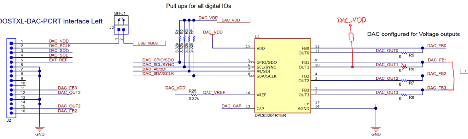
    DAC63204EVM-Board

    I only removed R6, so DAC1 is used as comparator and DAC3 is used to supply DAC1_FB1. I added a Pull-Up Resistor at DAC_OUT1, because I want to use this output in Open-Drain Mode.

    Configruration:

    DAC1:

    • Marging-High: d1638 (2V Hysteresis at 5V VDD)
    • Marging-Low: 0
    • VOUT_CMP_CONFIG:
      • VOUT_GAIN_1: 1
      • CMP_1_OD_EN: 1
      • CMP_1_OUT_EN: 1
      • CMP_1_HIZ_IN_DIS: 1
      • CMP_1_INV_EN: 0
      • CMP_1_EN: 1
    • CMP_MODE_CONFIG: 0b01 (Hysteresis Mode) 

    DAC3 as DAC-Output to supply DAC1 Feedback and triggering hysteresis witch latch.

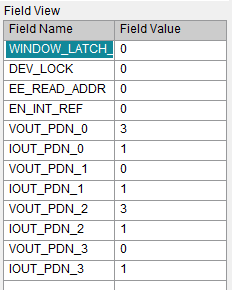
    COMMON_CONFIG Register:

    Now I am increasing the output voltage of DAC3 (red) and DAC1 comparator output (yellow) triggers at 2V.

    When triggering RESET_CMP_FLAG_1 in COMMON_DAC_TRIGGER, nothing happens, because the input of DAC_FB1 is still over the threshold. I can read out CMP_STATUS, the flag CMP_FLAG_1 says 0. So far okay.

    When I set the output of DAC3 lower than the threshold (to 1.6V), the Output of DAC1 is still LOW, so latch is working here (as long I don’t set the DAC3 Output to 0V, then the DAC_OUT1 is going HIGH again as said in my first post). I can read out CMP_STATUS, the flag CMP_FLAG_1 still says 0.

    When triggering RESET_CMP_FLAG_1 in COMMON_DAC_TRIGGER, output of DAC1 is going HIGH again and in CMP_STATUS, the flag CMP_FLAG_1 says 1.

    But now if I trigger RESET_CMP_FLAG_1 again the output is changing again. The Input of DAC_FB1 is still below the threshold (at 1.6V). I can do this several times and output is always changing. I can do this, as long as the input voltage at DAC_FB1 is larger than 0V and smaller than the threshold set in marging-high.

    So I can toggle the output of DAC1 just by triggering the RESET_CMP_FLAG_1. Is this feature wanted in that way or is it a bug?

    Thanks for any help.

    Dani

  • Hi Dani,

    Let me verify this other behavior on a board I have.

    Regards,

    James

  • Hi Dani,

    Finally got a chance to check this and I can see the same thing on my end. Toggling the RESET_CMP_FLAG_1 bit causes the comparator to alternate between a triggered and non-triggered output.

    When it's "triggered" and latched by this reset bit, the latch can still be released by lowering the input voltage to 0V. However, I can't imagine that this is the intended RESET behavior.

    For now, I don't have a work around besides only sending the reset once when the comparator is latched low. I'll have to report this back so we can look at it deeper.

    Regards,

    James