ADS42JB46: SYSREF, SYNC, RESET related power rails and biasing

Part Number: ADS42JB46
Other Parts Discussed in Thread: ADS42JB49, LMK04828, LMK04808

Hello, 

I'm trying to create a schematic for my ADS42JB49 and I'm running into the following problem : 
1. What are the power rails related to the pins SYSREF, SYNC and RESET? We have AVDD, AVDD3V, DRVDD and IOVDD..
2. In the ADS42JBXXEVM-SCH_D.pdf , we have the following termination for the LVPECL SYSREF and SYNC: 
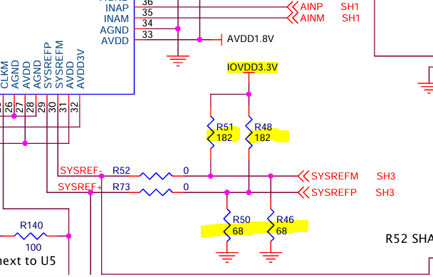
image.png
Why the use of IOVDD3.3V that is not used at all by the IC? Why isn't the IOVDD1.8V used in this case, with the resistors 100ohm instead to get the necessary Vcm of 0.9V? Something like below : 
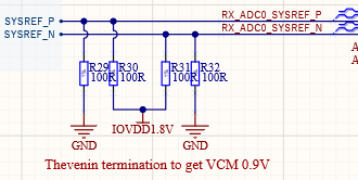
image.png

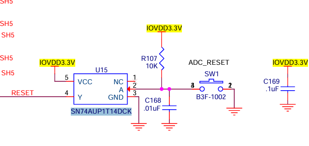
3. For the RESET pin, why the use of the inverter? Can't a simple pushbutton between the RESET pin and IOVDD1.8V suffice? image.png
Thank you, I hope to get some kind of response on this.

  • Hello,

    Please allow me to review your questions and get back to you. I will try to answer this by early next week.

    -Kang

  • Hello

    1. What are the power rails related to the pins SYSREF, SYNC and RESET? We have AVDD, AVDD3V, DRVDD and IOVDD..

    SYSREF and SYNC are in the AVDD domain, while Reset is the IOVDD domain. Please advise the background of your question. I am not clear on the rails would be related to these GPIO functionalities.

    2. In the ADS42JBXXEVM-SCH_D.pdf , we have the following termination for the LVPECL SYSREF and SYNC: 

    We recommend terminate the SYSREF based on the clock driver output termination methodology. The LMK04828 datasheet has certain specifications for the SYSREF and the associated termination voltage. 

    3. For the RESET pin, why the use of the inverter? Can't a simple pushbutton between the RESET pin and IOVDD1.8V suffice?

    Reset is active high. Push button, once pressed, connects to ground. Therefore, the inverter needs to invert the low signal to high signal. 

  • Hello, 
    Sorry I don't even know how to reply on this thread. 
    SYSREF and SYNC are in the AVDD domain, while Reset is the IOVDD domain. Please advise the background of your question. I am not clear on the rails would be related to these GPIO functionalities.

    As I am designing the card and those signals need to be biased to the correct voltages, I need to know what power rails they depend on in order to not mix up different power rails and potentially contaminating them. 

    We recommend terminate the SYSREF based on the clock driver output termination methodology. The LMK04828 datasheet has certain specifications for the SYSREF and the associated termination voltage. 

    Hence my question. In the datasheet for the LMK04828, they only mention DC coupling but they never showed any real applied solutions, only AC coupling. And again, IOVDD3.3V is not even powering the output stage of the LMK04828 (the Vcg) so why they are being used to bias these signals? And if AVDD (AVDD1.8V or the AVDD3.3V?) is the power rail for these inputs, why are they not used in the biasing scheme? 

    Reset is active high. Push button, once pressed, connects to ground. Therefore, the inverter needs to invert the low signal to high signal. 
    I think you misunderstood what I was saying : 

                  IOVDD 1.8 V
                       |
                       |
                  [ PUSHBUTTON ]
                       |
                       |
                       +---------> RESET pin
                       |
                    [ Rpull-down ]
                       |
                       |
                      GND

    This is a typical circuit for active high inputs that I know. Why did TI include an active component (the inverter) on the dev board? 

    All these questions are because : I am trying to design a board that costs a lot and I have a very small error margin. I can't afford to just blindly copy your devboards without understanding the fundamentals behind the design choices. 

  • Hello,

    Thank you for your reply.

    I also wanted to bring to your attention about a newer part that will perform better.

    https://www.ti.com/product/ADC3648

    Do you absolutely need JESD204B connection? If not, would you like to check out the link above?

    ~~~~~~~~~~~~~~~~~~~~~~~~~~~~~~~~~~~~~~~

    Regarding the LMK04828 termination:

    You may post a related thread (i.e. + Ask a related question) Yellow Button above, and post a question on the LMK04828 design. I believe at the time the designer of this EVM utilized the recommendation from the LMK04808 termination

    https://www.ti.com/lit/ds/symlink/lmk04808.pdf

    ~~~~~~~~~~~~~~~~~~~~~~~~~~~~~~~~~~~~~~~~~~~~~~~~

    Regarding reset circuit, all you need is an active HI signal. I do not have history of the original designer on why he/she used an inverter. Your circuit would work just fine. I would recommend a debounce circuit to avoid rining of the reset. 

    -Kang