ADS1285EVM-PDK: Correct Config setting

Part Number: ADS1285EVM-PDK
Other Parts Discussed in Thread: OPA1632, ADS1282, ADS1285

What are the correct register map config settings for unity gain ?

I have configured the input with a balanced OPA1632 this setup is veryt similar to the ADS1282 EVM same component values etc,

PGA_GAIN is GAIN_1

What are the correct GAIN 0 Gain 1 and GAIN 2 settings.?

In addition what are the settings for DC block or min frequency hi pass?

CONFIG0 = 00011010

CONFIG1 = 00000000

HPF0 = ????????

HPF1 = ????????

OFFSET0 = ????????

OFFSET1 = ????????

OFFSET2 = ????????

GAIN0 = 00000000

GAIN1 = 00000000

GAIN2 = 01000000

DIG_I/O = XXX0000X

SRC0 = 00000000

SRC1 = 10000000

Basically I donot see where the registers affect real responses For example if I want unity gain it seems that GAIN2 has to be set at a value the best I have is written above.

Also what freqrencies doe the HPF codes relate to?

  • Hello Shane,

    For Gain=1, use the default register settings, as you have shown above.

    GAIN2=40h
    GAIN1=00h
    GAIN0=00h

    Same for the offset values, use all default, which should be 00h.

    OFFSET2=00h
    OFFSET1=00h
    OFFSET0=00h

    The HPF1 and HPF0 registers set the high-pass corner frequency, but are only used when the high-pass filter (IIR) is enabled by setting the FILTR[1:0]=11b in the CONFIG0 register.  Since you have the filter set to FIR output, FILTR[1:0]=10b, the HPF1 and HPF0 settings have no effect on the output code.  You could set these to any value, but just leave these at the default values of HPF1=03h and HPF0=32h.

    Since you want a gain=1, use all default power-up reset values for all registers except the CONFIG registers.  Update CONFIG0 for the desired data rate.  CONFIG1 should be set to input1 (default) for external connections on J12.  Since you are using the EVM with a 4.096V reference, the REF[1:0] bits should be set to 01b as well.  (Looks like you have the CONFIG1 set to 00h, which would produce incorrect readings with a 4.096V reference.)

    CONFIG0=00011010b
    High power mode
    2000sps
    Linear phase FIR
    FIR output filter

    CONFIG1=00001000b
    Input1
    4.096V reference
    PGA gain=1

    Regards,
    Keith Nicholas
    Precision ADC Applications

  • Using 5V reference, I need to block DC only since the frequencies I am measuring are close to dc up to 20Hz. What is the lowest Fc of the HiPass?

    And Thank you for the Unity Gain settings confirmation. If I have differential -6dB into the OPA1632 feeding the ADS1285 EVM with Vocm connected I get -42dB in my spectral analysis

  • Delete last message re -42dB My mistake!! i get -6dB at 100Hz per input

    Need more instruction on DC elimination as close to lowest frequency as possible Thank you 

  • Hello Shane,

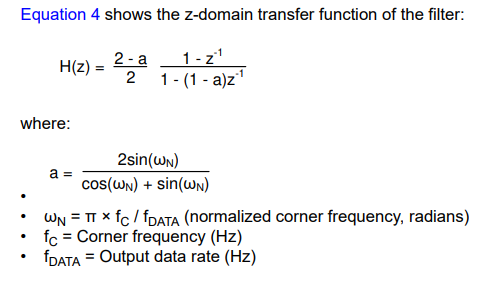
    You can manipulate equations 4 and 5 to calculate the high-pass cutoff frequency based on the register value HPF and data rate fdata.


    HPF[15:0]=a*2^16

    fc = fdata/Pi*ATAN[HPF/(2^17-HPF)]

    The lowest corner frequency as a function of the data rate fdata will be with HPF=1.

    fc-min = 2.4285*10^-6 * fdata

    fc-min(2000) = 2.4285*10^-6*2000 = 0.00486Hz

    However, note that using the IIR filter at extremely low frequency will result in a large settling time for any step input voltage change.

    For example, a 0V to 1V step input change will require n conversion periods to settle to within a give percentage.

    1% settling (x=0.01) with HPF=1 (minimum cutoff frequency) will require:

    n=ln(x)/ln(1-HPF/2^16)

    n=ln(0.01)/ln(1-1/2^16)=301802 conversion periods. 

    At 2000sps, this will take 151 seconds.  This number is similar to an RC analog high-pass filter at this same frequency.

    Regards,
    Keith