Hello dear,
I have using msc1210Y5 controller, i have configuring UART0,ADC,Timer0 isr, it was working separately, but both enable across it will not work
ADC and uart 0 work but timer 0isr affected. if i have off adc in PDCON register, timer o isr is working but UART 0 is affected, what can i do. i gave configuration
bellow. if any configure document have please send me.
char ADC_Setup1(void)
{
int deci=1728;
// USEC=10;
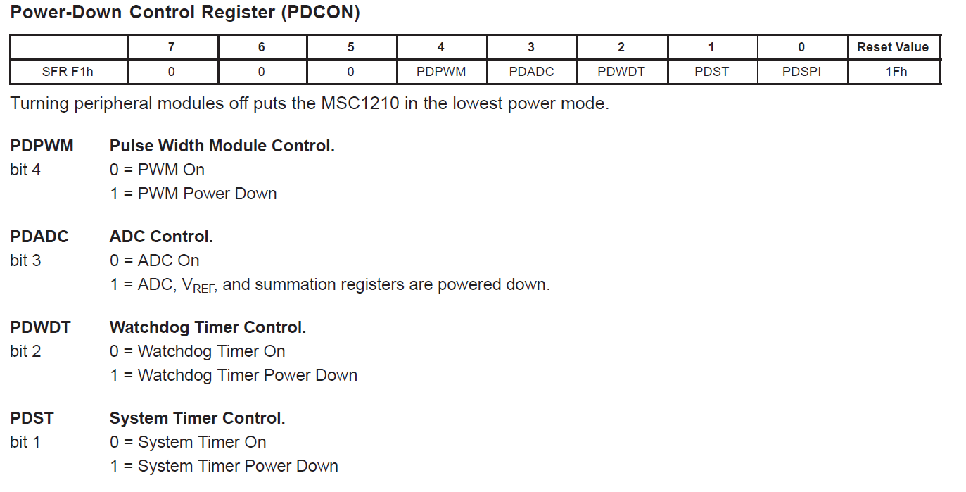
// PDCON = 0xff;
PDCON = 0x17;//17
// PDCON = 0xf5; // ADC On,PWM Power Down,SPI System Power Down,System Timer Power Down,Watchdog Timer Power Down
AIE = 0x20; // Enable Auxillary A/D Interrupt
EICON = 0x60; // EAI = 1;
ACLK = 0x04; // 4 ->687khz , 16 ->168 khz , RC ->1.5 khz
ADMUX = 0x23; // AIN 2 is +VE and AIN 3 is -VE DIFFERENTIAL INPUTS
ADCON0 = 0x37; // 37Gain is 128(PGA0,PGA1,PGA2)
ADCON1 = 0x41; // 71 31 Voltage Reference is 2.5v,Internal Voltage Reference On (default).
//ADCON2=0xc0;// deci & 0xff;//0Xc0;
// ADCON3=0x07;//(deci>>8) &0x07;
return(1);
}
void Timer0_init()
{
//Make INT1 edge triggered
TCON |= 0x04;
//this global variable track the number of times the Timer 0 timed out
timer_0_overflow_count = 0;
count_start = 0x200;
TMOD = 0x19;
CKCON = 0; //Select Divide by 12
IE = 0x86;
TH0 = 0x80;//count_start / 256; //set THO for timer0
TL0 = 0x00;//count_start % 256; //set TLO for timer0
TR0=0;
TF0=0;
/*
EA = 0; // disable all interrupts
TR0 = 0; // stop timer 0
TMOD = (TMOD & 0xF0) | 0x01;
// TL0 = 0xFE;
// TH0 = 0x4B;
TH0 = 0x80;//count_start / 256; //set THO for timer0
TL0 = 0x00;
ET0 = 1; // enable timer 0 interrupt
TR0 = 1; // start timer 0
EA = 1;
*/
}
void interrupt_timer0 ( ) interrupt 1 using 1
{ /*This ISR is called when a type 1 interrupt causes the processor to vector
into the code segment address 0x0006.
Register Bank 1 is used, as opposed to the default Register Bank 0.*/
IE &= 0x7f; //disable global interrupt
timer_0_overflow_count++; //Track number of times this ISR is called
//Reinitialize Timer 0 counters
TH0 = 0x80;//count_start / 256; //set THO for timer0
TL0 = 0x00;//count_start % 256; //set TLO for timer0
IE |= 0x80; //enable global interrupt
//IE |= 0xf0;
TF0=0;
TR0=1;
}
void setport1(void)
{
/* P1DDRL &= 0x0f;
P1DDRL |= 0x70; //P12 input, P13 output
CKCON |= 0x10; // Set timer 1 to clk/4
// TH1 = 256 - XTAL/4/16/BAUDRATE;
TH1 = 0xF7; //19200 bps @11.0592MHz
SCON1 = 0x50; //SCON: Async mode 1, 8-bit UART, enable rcvr; TI=CLEAR, RI = CLEAR
EICON |= 0x80; // Set SMOD0 for 16X baud rate clock
TMOD = (TMOD & 0x0F) | 0x20; // Timer 1 (Mode 2, Gate=0, internal clock)
TCON |= 0x40;*/
T2CON = 0x34; // Use Timer 2 as baudrate generator
RCAP2H = (T2RELOAD >> 8); // baudrate reload factor
RCAP2L = T2RELOAD;
SCON0 = 0x50; // enable serial uart & receiver, TI=SET for printf compatibility
PCON |= 0x80; // double baudrate for UART0
IE =0x98;
IP=0x10;
}
i want uart 0,adc, timer 0 init and config code and document.
Thanks and regards,
Ramesh k