This thread has been locked.

If you have a related question, please click the "Ask a related question" button in the top right corner. The newly created question will be automatically linked to this question.

Seeing "plateau" values at 0x__FF intervals in ADS8319 output

Other Parts Discussed in Thread: ADS8319

Hello -

We are using an ADS8319 and I am seeing a kind of "plateau" effect in the digital values read from the device.

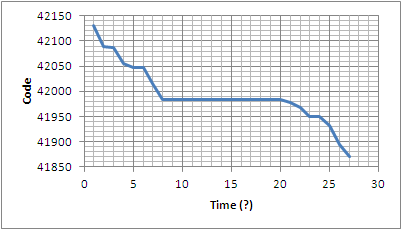
For example, for a slowly declining input voltage signal, the digital values will also slowly decrease until they reach a value where the lower byte is equal to 0xFF; at this point the value gets stuck for between say 2 and 7 subsequent samples. After being stuck for this brief period, the digital values will return to a normal, expectedl slow decay, matching the input voltage.

Here is an example of a contiguous set of A/D digital values to illustrate the problem:

A493
A469
A468
A448
A43F
A43F
A41F
A3FF
A3FF
A3FF
A3FF
A3FF
A3FF
A3FF
A3FF
A3FF
A3FF
A3FF
A3FF
A3FF
A3FA
A3F0
A3DE
A3DE
A3CD
A3A7
A38F

The repeated value is always 0xFF in the low byte; the high byte varies, so there are several places where the digital numbers form the plateau.

The number of times that the value repeats varies from 0 to 7 depending on the slope of the input voltage..

I suspected a SPI bus reading problem of some kind, but a scope actually shows the FF values being emitted from the A/D's SPI during readout.

I am using a 4.096V reference, which looks clean on the scope.

Any idea what might be happening? Thank you for any thoughts about this.

  • Hi Lawrence,

    Thanks for those details! I think you've eliminated possible issues on the digital side of the device. Have you looked at the analog side?

    What is your voltage source providing this decaying ramp, perhaps it is an unclean DAC output? Even with the decaying codes you don't seem to have constant slope, is this to be expected?

    I would be interested to know if your buffering or filtering your input. If you have a schematic you can show it would be helpful.

    What is your sampling rate? If you are using a fast sampling rate you may need a fast buffer to correctly charge the internal sample and hold capacitor of the ADC to the correct value within the acquisition time.

    Regards,
    Chris

  • Chris -

    Thank you for the quick response! However, we were able to fix this problem in the following way:

    Our PCB has separate analog and digital ground planes. We initially had the ADS8319's pin 5 tied to our digital ground, which produced the results that I posted above. When we moved pin 5 to analog ground, this "plateau" effect disappeared completely. So in the original configuration, the reference voltage source and the A/D were not grounded at exactly the same spot. A ground noise spike at the wrong time must have caused the SAR to step over a bit and never recover?

    For your other questions, the voltage source is analog in nature with a varying slope, not originally derived from a digital source; we are using the TI recommended filter network on the Vin pins, and have a low impedance source driving the Vin pins. The Reference, analog and digital supplies are bypassed near the A/D as recommened by TI.

    Again thanks for the analysis and quick response.


  • Excellent! Thank you for sharing your solution!

    Chris

  • Hi

    Not sure if I should be continuing this old thread, but I have a mostly similar issue.

    I'm trying to read the output of a Freescale MPX4250 sensor through ADS8319. It looks like sometimes 4 to 10 LSB of the output digital value gets stuck on a fixed value of 1111 to 1111111111.

    Now, I haven't yet tried checking the SPI interface through a scope, also I am not using a very good reference for the prototype I'm working with (I'm using a seperately regulated source as both analog supply and reference). My +IN is from the sensor directly which has it's own buffer integrated; through a low impedance RC filter recommended from the sensor manufacturer. I have a combined and very low impedance ground plane and the GND of the ADS8319 is connected to that. -IN is connected with the ground through a 5ohm resistor as shown on page 21 of ADS8319 datasheet.

    What makes me think this is similar issue is that, if I remove the 5ohm resistor and connect the -IN to GND directly this issue goes away. Also, sometimes even with the resistor, this issue doesn't happen.

    Now, I am a student, and I am experimenting with this setup to use it on a project for my thesis. So, if anyone could give me some idea on what's happening and why?

    Thanks

  • Hi Swapnil,

    Could you please share your schematic? Is it possible for you to measure the voltages on the supply, reference, +IN and -IN pins of the ADC when it is in the condition you describe?

    Thanks,
    Harsha

  • Here is the schematic. Also, I've measured the voltage. The Supply voltage is 4.99v, Reference is also 4.99v. +IN is variable and mostly 1.79v when I measured. -IN is 0v. In my current design I haven't put any decoupling caps in +IN and -IN. I guess I have to rebuild a board with that and test it for results. Thanks.

    SBv0001.PDF
  • Basically, if the lower 10 bits are always saturated then the ADC is unable to resolve an input level that is less than 2^10/2^16 of its full-scale input range. In other words, the ADC is behaving like a 6-bit ADC. This sort of thing is generally associated with excessive drops in the reference voltage due to changing cap loads on the ref pin during the conversion process. Large bypass caps are required for good load regulation of the reference voltage. In your case the 4.7uF may be marginal. I would recommend trying out a 22uF cap or greater to see if it makes a difference. Also, at what sampling rate are you using the ADC? Your input RC circuit needs about 3.2ms (12 to 13 time constants) to settle fully (error < 1LSB). So if you haven't tried it already, please decrease your sampling rate (use sampling period >3.2ms) and let me know if that makes a difference.

    Thanks,
    Harsha

  • Sorry I was away from the project for some time. Also sorry for wasting your time, as we've found that the problem was originated from some quality issues of the soldering of the ADC to PCB. We've built a new board and couldn't recreate the problem anyhow in that new board.

    Thanks for your reply

    Swapnil