This thread has been locked.

If you have a related question, please click the "Ask a related question" button in the top right corner. The newly created question will be automatically linked to this question.

Reading data for the ADS8505

Other Parts Discussed in Thread: ADS8505, ADS7885

Gentlemen,

I am using the ADS8505 as shown in figure 21, page 10 of "SLAS180B-September 2005- Revised June 2007" document. With a -10v analog input,  the hex code reading is 0000, at +10v the code is FFFF.  This is clearly not what is stated in table 2 "Ideal Input Voltages and Output Codes".  Please advise...

By the way, is this part recommended for new design?  If not what would you recommend?

Thank you for your help.

Serge Faublas

  • Hello Serge,

    Welcome to the Precision Data Converter Forum.

    First, thanks for choosing the ADS8505, and if it fits the requirements of a new design, we recommend using it.

    Regarding the data format issue, it appears it is software related as the data format should be two’s complement.

    This can be verified with a negative voltage input and probing MSB, R/C, and BUSY. After toggling R/C and waiting for /BUSY to go high, a negative input voltage should make the MSB pin to be high.

    The MSB pin can be either pin 6 or pin 15 depending on BYTE (pin23) logic value.

    Also, I recommend using +-9.9V instead of +-10V to check the converter or calibrate. +-10V could be out of range if the reference value is below 2.51V.

    How is the data read? Are all the bits read at the same time? Or are two sets of 8bits read with BYTE (pin23) toggle?

    Is data stored in a signed variable? Is there any casting in your code?

    About the input, are you using a low impedance source, for example an op-amp, to drive the 200ohm resistor?

    Thank you,
    Rafael

  • Gentlemen,

    Mystery solved... Please disregard my previous statement: the part operates as advertized; it does returns data in 2's complement format: -10v gives hex code 8000, +9.9999v gives 7FFF.  My firmware was making the conversion before presenting the hex code.

    Is the ADS8505 recommended for new design?  If not, your recommendations will be greatly appretiated.

    Thank you in advance for your cooperation.


  • Hello Rafael,

    Your reply coincided with my issue retraction... Thank you for your answer.  As stated, I did not realize that my code was converting the 2's complement data before presenting it...

    Thank you once again for your input and for recommending using the part.

    Serge.

  • Gentlemen,

    Thank you for your assistance.

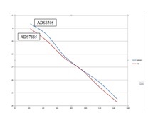
     The ADS8505 is operational in my project.  However, I did a side by side comparison with the ADS7885 (being replaced by the ADS8505) and found some linearity issues. The following graph illustrates the point:


    Data plotted: Voltage reading as a function of sample height.

    height(mm)

    ADS8505

    ADS7885

    22

    3.033359

    2.995937

    45

    2.950282

    2.902963

    70

    2.785125

    2.770738

    95

    2.678596

    2.676102

    120

    2.580634

    2.543627

    145

    2.45107

    2.426787


    The curve obtained with the ADS7885 (in red) seems to be more linear.  I looked at the specs for the ADS 8505 and saw that there is an “Integral and also a differential linearity error” specified (+-1.5LSB and +-1LSB respectively); my understanding: about +-457.6µV for 10V input.  For the ADS7885A there is an “Integral nonlinearity specification of 0.003% FSR; my understanding about 300µV for 10V input.  Is this what I am dealing with?

    Can you recommend some improvements or a better A/D (same foot print or not) to address the linearity issue?

    Thank you in advance.

    Serge