Hi all,
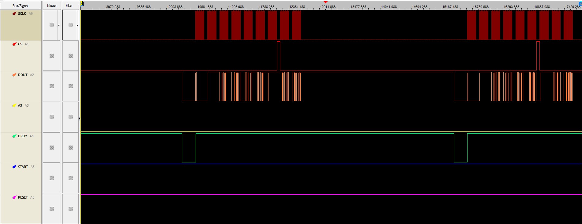
I added below signals and request your help to solve this issue. My signals look synchronizied with each other but the signals are not clean enough, I set triggering and it seems the pulse width of DRDY and CS signals are also changing. I am using ADS1298 development board with EVM 5515.
My SCLK signal seems not clean, I read meaningless data on DOUT. I use internal clock of ADS1298 by setting CLK_SEL, therefore ADS clock is 2.048 MHz. Conversion rate is 2 KSPS. SCLK is set to 500 kHz at first to ensure two byte opcodes (WREG and RREG) will be executed properly (wait 8 clock cycles between bytes). For the SPI data operation SCLK is 4 MHZ. For 2KSPS, minimum SCLK should be 2K * 9 * 24 = 432 kHz, well below 4 MHz (I also tried lower SCLKs close to 500 kHz).
START signal is controlled with GPIO4 of 5515, RESET is controlled by GPIO1 of 5515 and both are proper. I set RESET high and give a RESET pulse and take it back to high and can observe all these signals.
GPIO_write(hGpio,CSL_GPIO_PIN1,setVal); //RESET is high
wait(1000);
GPIO_write(hGpio,CSL_GPIO_PIN1,resetVal); //RESET is low
wait(1000); //RESET pulse
GPIO_write(hGpio,CSL_GPIO_PIN1,setVal); //RESET is high again
wait(74000);
wait(74000);
GPIO_write(hGpio,CSL_GPIO_PIN4,resetVal); //START is off before initializing SPI and ADS1298
wait(10);
wait(74000); //end of START reset, now initialize SPI and set configuration...
GPIO_write(hGpio,CSL_GPIO_PIN4,setVal); //START conversion
wait(100000);
I am sorry that I only have two scopes to show signals. I will try to find a multiple digital channel scope by Monday and will add extra more captures showing all signals together.
I can give all other necessary information if you ask me to.
Contributions will be appreciated.
Regards.
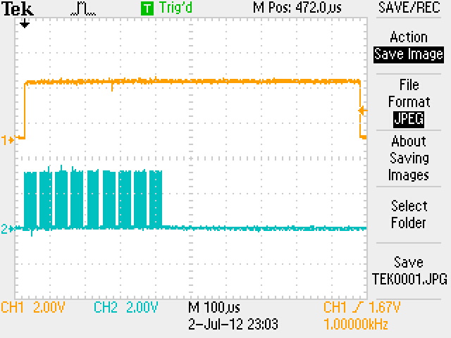
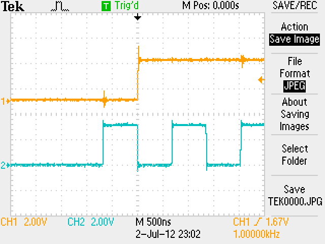
SCLK with CS signal #1:
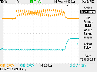
SCLK with CS signal #2:
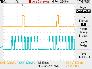
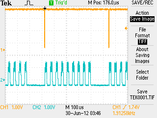
SCLK with DRDY signal #1:
SCLK with DRDY signal #2:
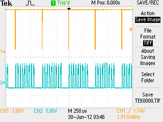
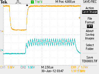
SCLK with DRDY signal #3: