Hello All ;
I am happy to join TI forum ; I am digital engineer I have good analog background ; We would like to design an AED using ADS1292R ( good chip) ; Since ECG signal are a bit complicated for me ; I have some questions before getting in the design .
- Do I need to use amplifiers to amplify ECG signal before ADS1292r? If yes ; do you suggest cisruits or application notes?
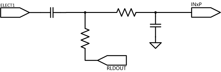
- My design will be one lead ecg ; only two electrodes; so how can i use pseudo RLD with ADS1292R ?
- In the kit of ADS1292R ; there are 3 digital filters impelmented ; IIR, FIR and notch ; where I can find the codes of these filters ?
I looking to get helped and guided in the forum ;
Thank you in advanced .
Hector