This thread has been locked.

If you have a related question, please click the "Ask a related question" button in the top right corner. The newly created question will be automatically linked to this question.

How to verify correct data from ADS1292R?

Other Parts Discussed in Thread: ADS1292R, ADS1292

Hi,

Here's my setup- ADS1292R with internal clock enabled, 512KHz SPI frequency, and Start pin tied Low.

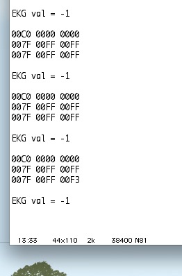
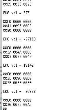
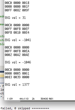
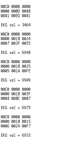
On startup I send the START opcode, then read in the data ( which is 24 bit status, 24 bit channel 1 , 24 bit channel 2). I get the Status perfectly, 0xC00000, and I get values for the channels.

Is there any way to test that I'm reading the right values?

Am I supposed to read some specific number when I short the two leads for a channel? Or am I supposed to get 0 if I connect both leads to ground? Any other ideas for tests to verify that I'm reading the right data would be very appreciated.

Thank you

  • Hi Eric,

    The output code is binary two's complement on the ADS1292, so shorting the inputs should give you output codes in the neighborhood of 0xFFFFFx to 0x00000F - take a look at Table 10 on page 27 of the data sheet.  You could also try applying a simple DC input - try to compare the output code against the input voltage again referring to Table 10.

  • Hi,

    For leads I'm just using regular 30 gauge wire. When the leads aren't shorted to each other I get the following output - usually 0x7FFFFF, but occasionally different values. Is this normal behavior from the ADS chip or should I check my SPI lines with a logic analyzer to see if data is being corrupted somehow. 

    My data output is as follows - first line is Status, then Channel 1, then Channel 2. Ignore the EKG Val = whatever, i didn't finish that bit of code yet.


    When I short the two leads of a channel ( I shorted Channel 1)  to each other,  the values are all over the place.


    Shouldn't the value for a shorted channel be very close, if not equal to 0? Also, why would it be, as you said,  "in the neighborhood of 0xFFFFFx to 0x00000F"?


    Thanks for all the help, this is my first experience with EKG chips. Much appreciated.

  • Hi Eric,

    Shorted inputs would be 0V differential, so the ideal code should be 0x000000 - there may be some counts of noise which is why I gave you the range of 32 codes as a ball park expectation.  Your numbers are a bit farther away from what I would expect to see though.   Unless you're saturated at positive or negative full scale, you will see some fluctuation in codes.  Verify your power supplies are correct and that you have the expected reference voltage at the VREFP pin (either 2.4 or 4.0V with respect to AVss) and let us know what you see on the VCAP pins.

    Go ahead and send scope shots (from an oscilloscope, not a logic analyzer) and we'll take another look.  Don't fixate too much on 'EKG chips' just yet, the ADS1292R is still a data converter and it works just like any other delta-sigma ADC.  

  • Weird voltages on my end...

    Vcap1 - 1.20V

    Vcap2 - 5.25V

    Vrefp - basically 0, 12mV

    Vrefn - common gnd, so 0

    My supply voltage to the chip is 3.3V. I have a .1uF and a 10uF cap between Vrefp and Vrefn. 

    I'm pretty lost what could be wrong, especially the 5.25V showing up - I don't have any voltage that high anywhere in circuit.

  • There is a charge pump in the device, so the 5.25V may be right - will check that in the AM.  VrefP is off though (if measured WRT to AVSS), so let us know your configuration detail.  Have you enabled the internal reference according to your configuration register read back?

  • Thanks for the reply! You are very good at what you do!

    Now I wrote to the CONFIG2 register and enabled the internal reference. Now I see a 2.4V on the Vrefp line.

    The lines  of the first channel are shorted to each other on this session.

    Does the output seem correct to you?  ( Again, first line is status, second line is the first channel, last line is the 2nd channel)

    EDIT:

    And here's the output when I short both leads of Channel 1 to each other AND ground them. All low numbers for Channel 1

  • Hi Eric,

    Thanks!  Your current conversion results look much closer to what I'd expect to see with shorted inputs to the ADS1292R.  Next step - try the 'input short' configuration and you should see the offset values internal to the part along with the test voltages..  From there, try your 10Hz sine wave again and let us know what you see.  If your are configured for a uni-polar input, you'll have to accommodate the CM voltage with a bit of offset from your signal generator (i.e. Vref/2). 

    EDIT: Next step - try the 'input short' configuration and you should see the offset values internal to the part.  From there, try your 10Hz sine wave again and let us know what you see.  If your are configured for a uni-polar input, you'll have to accommodate the CM voltage with a bit of offset from your signal generator (i.e. Vref/2). 

  • Hi Tom

    I responding to this thread as the query is similar to the one I posted in the link below. 

    http://e2e.ti.com/support/data_converters/precision_data_converters/f/73/t/248993.aspx

    As mentioned in the link above, my data acquisition system uses cascaded ADS1292 & ADS1292R connected to CC2541 over SPI.

    System uses unipolar voltage (3V) and internal reference is enabled. I have checked for following voltages on pins of both the ADS1292(R)

    VREFP=2.42V

    VCAP2=4.96V

    VCAP1=1.1For DC Test configuration (config2: 0xAA) with Gain of 6 (default), I get the following output (status; chan 0; chan 1)

    Sample output in Iteration-1:

    C0 20 00; FF A8 E4; FF A9 5F

    C0 20 00; FF A8 E4; FF A9 76

    C0 20 00; FF A8 EB; F8 04 00

    C0 20 01; 80 40 01; FF 51 EF

    C0 20 06; 01 00 07; FD 46 B7

    C0 20 00; FF A8 EC; FF A9 C0

    C6 01 00; 07 FD 47; F7 FD 40

    Sample output in Iteration-2:

    C0 20 00; FF A7 67; FF A7 E7

    C0 20 00; FF A9 01; FF A9 6E

    C0 20 00; FF A8 F5; FF A9 65

    C0 20 00; FF A8 D9; FF A9 6E

    Is the above data output as expected for TEST Mode DC?

    Occasionally, I get output like below which I think is not correct and I'm unable to conclude if the data was sampled wrong or the ADS1292 sends the test data in this manner. Can we decide to discard these samples based on the first 24-bit status field? Does the ADS1292 chip send test data samples with Lead off status bits occasionally set as seen in the below samples?

    C0 00 60; 00 00 7F; FD 34 FF

    C0 00 0C; 00 00 0F; FA 8E BF

    C0 03 00; 00 03 FE; A3 47 FE

    Thanks

    Ganesh