This thread has been locked.

If you have a related question, please click the "Ask a related question" button in the top right corner. The newly created question will be automatically linked to this question.

Configuring an ADS1247...

Other Parts Discussed in Thread: ADS1247

Hi,

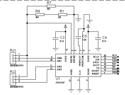
I build this circuit to work with two 3-wires PT100:

Well, now I wanna read AVDD (or DVDD) value, then 1st PT100 (RJ11_1) and then the 2nd PT100 (RJ11_2).

Let's start from the beginning: AVDD measurement!

I did:

WriteSPI1(0x40); // WREG command
WriteSPI1(0x03); // 4 registers - 1 = 0x03
WriteSPI1(0x01); // MUX0
WriteSPI1(0x00); // Vbias
WriteSPI1(0x26); // MUX1 -- AVDD operation
WriteSPI1(0x08); // SYS0

//Send command WREG (0x40) to write the regs and IDAC0 IDAC1 (+0Ah)
WriteSPI1(0x4A);
WriteSPI1(0x01);
WriteSPI1(0x06); //IDAC0
WriteSPI1(0x01); //IDAC1 (AIN0 AIN1)

Then, to read:

WriteSPI1(0x12); // Command RDATA ==> Read data once

for(x=0;x<3,x++)
{
   WriteSPI1(0xFF); // Command NOP ==> Wait
   data[x] = ReadSPI1();
}

The ADS1247 always answers me 0x7F-0xFF-0xFF. :(

Thanks,

Daniel

  • Hi Daniel,

    When using the IDAC excitation currents, the internal reference must be enabled.  The code snippet above appears to be correct, where you are connecting a PT100 sensor on the 3 wires setting the IDAC1 and IDAC2 to 1000uA, flowing through AIN0 and AIN1, producing a ~1.6V reference across the 833 Ohm resistor.

    However, in order for the internal reference to work, the VREFCOM pin needs to be connected to an AC GND.  In your case, VREFCOM needs to be connected to your analog Ground (AGND) through a short, low inductance trace.  The VREFOUT pin requires a capacitor in the range of 1uF to 47uF for stability purposes. The capacitor needs to be connected between VREFOUT and VREFCOM.  Please refer to p29 of the datasheet for more information.

    Please let me know if this does not solve the problem.

    Thank you and Best Regards,

    Luis

  • As you suggested me, I connected the VREFCOM pin to GND and connected a 10uF capacitor between VREFOUT and VREFCOM.

    But I still get the same answer: 0x7F-0xFF-0xFF. :(

    Look that I have this answer for AVDD measurement and not for RTD's readings!

    Thank you!

  • Hi Daniel,

    I forgot to mention, the ADS1247 is by default in the RDATAC (Read Data Continuously) mode when the device is powered up and the START pin is held high.  In RDATAC mode, the output conversions are automatically loaded in the output register, and the device will always output the data conversions once the DRDY signal goes low by sending 24 SCLKs.  In this mode of operation, the user must complete data retrieval before the next DRDY pulse, or the resulting data will be corrupt; therefore, in RDATAC mode, the user needs to monitor the DRDY signal to read conversions.

    If you don't want to monitor the DRDY signal and plan to use the RDATA command to read the conversions; a suggestion may be to issue first the SDATAC command (Stop reading data continuously)  to terminate the RDATAC mode.  After the device is in SDATAC mode, you may issue the RDATA command to read the conversion results.  Please refer to page 51 and 52 of the datasheet.

    Best Regards,

    Luis

  • Hi Daniel,

    1) Is the PT100 installed?  After enabling the internal reference, do you measure a 2.048V internal reference on the VREFOUT pin with an external meter? Can you measure the voltage across the 833 Ohm RBIAS resistor with an external meter?  Is the START and RESET pin held high?

    2) Are you able to read the configuration registers?  (Before attempting to read the register contents, please issue the SDATAC command)

    Thank you,

    Best Regards,

    Luis

  • Daniel,

    To use the supply monitor you must make sure the internal reference is turned on.  By default it is off.  As Luis has mentioned you must have a cap on the VREFOUT pins for the internal reference to work properly.   Also, as Luis mentioned, the internal reference must be on for the IDACs to work.

    Best regards,

    Bob B

  • Thanks for all this advises! And let me update my current status!

    I had two problems:

    First of all, the REFSELT Bits at MUX1 as "wrong" ('00'). I changed to '10' (Onboard reference selected).

    The second was the timing between some commands.

    Now it seems to be working... and I'm trying to understand my results.

    When I tried to do the AVDD Measurement (AVDD = 3.48V), the ADS1247 returned 0x405D1Eh as result (=4218142).

    Calculating... 4218142 * 4 * 2.048 * (1 / ( 2^23 - 1 )) = 4.1193V

    Something seems to be wrong here, don't you think?

  • Daniel,

    The supply monitor is a rather course measurement as it is divided by 4 and this division is not precise.  Generally we see closer values than what you are seeing.  Is this a single point measurement or have you seen this over a series of measurements?  If there is a lot of supply noise you may see a lot of variance.  Have you looked at the DVDD supply to see if it is tracking?

    If you switched back to using your external reference from the IDAC sources, the reference would be a different value and the result would be much closer to what you would expect.  Verify that you are actually taking the system monitor measurement using the internal reference as opposed to the external one created with Rbias.

    Best regards,

    Bob B

  • Bob,

    I was doing a single point measurement and it didn't help!

    But your last message made me a little bit lost...I though I was using IDAC source and the internal reference.. did I?

    And using the PT100, should I use the external reference from the IDAC source with Rbias, right?

  • Daniel,

    I'm sorry for any confusion.  What I was asking about before is if you were just taking one measurement, or if you were taking the measurements in a continuous manner to see if the measurements were varying a lot between measurement readings.

    If you use the IDACs then you must turn on the internal reference to establish the reference used for developing the current sources.  You do not need to use the internal reference as the reference for the ADC.  There are two sections for the MUX1 register that must be set.  One to choose the reference used for the ADC (REFSELT), and the other to turn on and off the internal reference (VREFCON) which is required to be turned on when using the IDACs.  Normally you would use the reference created from Rbias when taking the temperature measurments.  You would then use the voltage created across Rbias as the reference voltage for the calculation of the output value for the ADC.

    To use the IDAC reference for your measurement and to measure the AVDD supply the MUX1 register should be set to 0x26 (internal reference on, REF0 selected, monitoring AVDD.)

    If you use 1mA from each AIN selected (2mA total) through a 3 wire RTD, then the current through the 833 ohm resistor is about 1.666V.  Using the values you showed us previously:

    Calculating... 4218142 * 4 * 1.666V * (1 / ( 2^23 - 1 )) = 3.35V

    This value is much closer to your stated voltage of 3.48V.

    Best regards,

    Bob B

  • I guess I'm understanding better... thanks! :)

    Now let's go to PT100's measurement, but I'm gonna start by hardware and configuration registers.

    Imagine that I wanna measure temperatures between -100ºC and +20ºC.
    The resistance of the PT-100 at -100°C is 60.3Ω and at +20°C is 107.8Ω. 

     My supply is 3V and I'm a little bit lost about the best choice for PGA and IDAC values. I'd also like to know if the calibration setting (OSC and FSC registers) could help me improving my results (improving the best dynamic range).

     Thanks 

  •  Hi,

     Thanks for the answer. I guess I'm understanding a bit better. :-)

     Now I'd like to know more about the PT100's measurement, once I wanna measure temperatures between -100ºC and +20ºC with 0.1ºC resolution.
    The resistance of the PT-100 at -100ºC is 60.3Ω and at +20ºC is 107.8Ω.

    My supply is 3V and I'm a little bit lost about the best choice for PGA and IDAC values. I'd also like to know if the calibration setting (OSC and FSC registers) could help me improving my results (improving the best dynamic range).

  • Hello Daniel,

    There are a number of factors to consider when selecting the RBIAS/REFERENCE resistor.  The RBIAS/REF resistor will be typically selected to bias the RTD at the middle of the analog supplies  (AVDD/AVSS) and the value will depend on the IDAC excitation current that is selected.  In general, when using an analog supply of 3.3V; the RBIAS would be chosen to produce a ~1.65V to 2V reference voltage.  In this case, this voltage is in the optimal range for a reference voltage for conversion and the RTD is biased at the optimal common-mode voltage at the middle of the AVDD/AVSS supplies... 

    In the case of the 3-wire configuration; only 1 IDAC current flows through the RTD sensor; however x2 IDAC currents flow through the RBIAS/REF resistor...Please refer to figures 2, 3 and 4 of application note SBAA180 (Application Note link is below)

    http://www.ti.com/general/docs/litabsmultiplefilelist.tsp?literatureNumber=sbaa180

    When selecting the IDAC excitation current, the user has to account different factors, such as sensor impedance, and account for the trade off between the resolution in the measurement and RTD sensor self heating.  The larger the excitation source the larger the output will be making the output easier to measure and increasing resolution.  However with RTD sensors, the larger the excitation current, the larger the self-heating effects will be; which will add to the measurement error cancelling out improvements in resolution.   Also, depending of the type of RTD element or probe used in the application,  dissipation constants may be in the range of 1mW/C to 60mW/C; therefore, the heat dissipation constant will vary greatly depending of the type of RTD probe used and the type of environment that will be measured in the application.  Some RTD probes tend to be physically large; and may be used to measure the temperature of a fluid.  These may tolerate larger excitation currents in the order of ~1mA with negligible effects due to self heating.  In contrast, RTD’s probes used to measure the temperature of gases may tend to be smaller in order to have faster response times.  These smaller RTD’s will be more sensitive to self heating.  For these cases, the user could consider using a smaller IDAC current setting such as 100uA to avoid self heating and scale the RBIAS/Reference resistor accordingly.

    Depending on the dissipation constant of the RTD element used and the medium you are trying to measure temperature, you will choose the IDAC current setting.  After this, you will then choose an RBIAS resistor that will generate a reference voltage (1.65V to 2V may be optimal when using 3.3V supply).  The PGA gain will be chosen depending on the RTD range and IDAC current setting.  For example, if you are using a 3.3V supply, and if you decided to use IDAC1 and IDAC2 set to 250uA after accounting for the sensor self-heating,  you will use a RBIAS resistor around ~3.3kOhm to generate the ~1.65V voltage reference.   The max RTD value expected at the given maximum temperature range in your example is ~107 Ohms at 20C; producing a differential voltage of ~26.75mV at the inputs of the device.  The full-scale voltage is given by +/-VREF/PGA. If you choose PGA=32V/V; the allowed full-scale is +/-51.5mV. 

    In most applications, the user will perform a self-offset calibration.  After initializing the hardware and configuring the device, (enabling the internal reference, IDACs, selecting the appropriate mux channel, and waiting for the reference voltage to settle) the user will issue a SELFOCAL command.  There is more information on pages 31 and 32 of the datasheet about the calibration routines.   On the ADS1247; the Full-Scale Calibration Coefficient is factory trimmed for each gain setting; providing a very small gain error of +/-0.005% typ; in most applications, the user will only perform a self-offset calibration or a system-offset calibration. 

    Thank you and Best Regards,
     
    Luis


  • Thank you for this wonderful explanation. It really helped me to solve the problem.

    In the next weeks, I'm gonna study a little more about Calibration and understand when and where this could be useful to me.

    Thank you very much!

    Best regards,

    Daniel 

  • Hi Daniel,

    Thank you very much for the feedback.

    Best,

    Luis

  • Hi, everybody. Sorry for this delay time, but I'm back with more questions and concerns! ;-)

    Let's start from the beggining. Nowadays, my schematic is this one below.

    1) Is this correct? Two 3-wire RTDs (PT100) will be connected at RJ1 and RJ2.

    The supply voltage is 3.0V. And my Rbias is 1.65kohms (3k3 // 3k3). My IDACs are configurated to generate 500uA each one (IMAG@IDA0 = 100).

    My PGA is 16 (PGA@SYS0 = 100), so my full scale is 1,65V/16 = 103,125mV. This allows me to measure high temperatures as 200ºC (± 175,8ohms), which generates me 87,9mV with IDAC=500uA ( 175,8ohms * 500uA = 87,9mV).

    My registers are:

    MUX0 = 0x08 (to measure RJ1) and 0x1A  (to measure RJ2) 
    Vbias =  0x00
    MUX1 = 0x20
    SYS0 = 0x44

    IDAC0 = 0x04
    IDAC1 = 0x01 (to measure RJ1) and 0x23  (to measure RJ2) 

     2) Are my choices consistent?

     3) What's my conversion equation? Voltage_In = ADC_Value * My_Full_Scale / (2^23-1)? My_Full_Scale =  103,125mV


    Thanks in advice

  • Hi Daniel,

    This looks ok, you just need to be careful with possible drift issues with the parallel resistors.  The Rbias for the reference should be a low drift high precision resistor.  The register settings look ok as does the equation.

    Best regards,

    Bob B

  • Thank you, Bob. But I'm still having unstable and inconsistent measurements.

    I'll check this link. I suspect that I'm having timing problems.

  • Unfortunately, I'm still having problems.

    I just receive 0x7FFFFF as answer after a RDATA command.

    I was taking a look at the voltage in Rbias, and I saw just a half of what supposed to be. In other words, I measured 0.825V instead of 1.65V, what is weird once my IDACs are set to 500uA (as I wrote a few posts ago).

    It's probably messing with all my settings, isn't it?

     Any idea? 

    Thanks in advice!

  • Hi Daniel,

    If the Rbias resistor is only dropping 1/2 the expected voltage then current is missing either by improper IDAC routing/configuration or improper wiring.  You can read back the register to see if the problem is an incorrect setting.  You should also be able to detect which current source is missing by either turning on/off current sources or by removing one of the RTD leads to see if the current through Rbias is no longer present.

    Best regards,

    Bob B