This thread has been locked.

If you have a related question, please click the "Ask a related question" button in the top right corner. The newly created question will be automatically linked to this question.

ADS1258 DRDY issue on shared SPI bus

Other Parts Discussed in Thread: ADS1258

Greetings,

I'm trying to acquire data using two ADS1258 on a shared SPI bus. I can communicate to both chips without problems and so I configured both ICs to convert in AUTOSCAN mode two channels each. The start pin is tied to high so the ADCs are constantly converting and each time that I need data I wait for the DRDY interrupt and then read the data with the CHANNEL_DATA_READ_COMMAND as recommended for a shared spi bus by the data sheet.

When reading the CS is just low for one of the ADCs but non the less the DRDY lines for both ADCs immediately assert high. This kind of behavior is not documented in the data sheet and as I need the line signals to identify what ADC I have to read from, this behavior is quite annoying. Hence I would like to understand if I'm dong something wrong here or if this kind of behavior is documented somewhere and I just missed it.

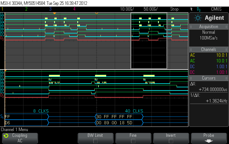
The following image shows the communication the bus. In the following I explain the signals in the graphic in order  of their appearance:
D0=PWR_ENABLE;
D1=SPI_CLK;
D4=MOSI;
D5=MISO;
D6=DRDY_ADC1;
D3=CS_ADC1;
D7=DRDY_ADC2;
D2=CS_ADC2;


Thank you for you input and consideration,

Gunter Kanitz 


  • Hi Gunter,

    One thing you should know about the ADS1258 is that it is not a true SPI interface, but rather, a SPI compatible interface. The biggest difference lies in the behavior of the /CS line.

    When /CS is brought high, the SDO is 3-state so there will not be any conflicts sharing the bus with other devices. However, the SCLK is not internally disconnected from the ADC digital interface. Therefore, when new data is ready and /DRDY shows a falling edge, as soon as SCLKs are sent, data will be shifted out. When /CS is held high in this condition, SDO is 3-state so you will not see the data being shifted out on the bus. If you were to bring /CS low, for example, 4 SCLKs after a /DRDY falling edge, you will start clocking out data at the MSB-4 point.  For that reason, we added a note 3 in the data sheet on Figure 57 explaining that there cannot be any SCLK activity between /DRDY low to /CS low to read back the data in channel data read direct using no command.

    So, if you are sharing a SPI bus across two ADS1258s, you will need to use the channel data read register format, requiring that a Channel Data Read Command is sent when you are ready to read back data. The Channel Data Read Command shifts the ADC new data into the output register to be read back at the completion of the command. So, if you have SCLKs on the SPI bus, while /CS is high (causing the data to shift in the ADS1258), you can reset the output register to the MSB with the Channel Data Read Command so that you begin reading back at the beginning of the data word. Unfortunately, this does not solve the issue of both /DRDY lines responding to your first SCLK. The only way to deal with that issue would be to use some sort of external logic to block SCLK from the device until ready to read from it. However, if you are using two ADS1258s synchronized and sharing the same master clock, the /DRDY should pulse together requiring you to only monitor the interrupt of one of the ADCs.

    Regards,

    Tony Calabria

  • Hi Tony,

    thank you for the quick and detailed response. Obviously I missed that information about the SCLK. I hope that in future versions of the data sheet this issue will be pointed out explicitly in the section "SPI bus sharing".

    Ciao,
    Gunter Kanitz 

  • Hi Gunter,

    Thank you for the feedback, we will try to make this clearer in the next ADS1258 data sheet revision.

  • I ran into the same issue a while back while processing 4 ADS1258's on a shared SPI bus.  My solution was to reset each ADC effectively staggering the times the DRDY lines would be active.  This can be done by separately controlling each RST line or issuing a RESET command via the SPI bus at offset times.  I currently have a shared RST line  so I issue a RESET command to start their data acquisition periods at different times.