Other Parts Discussed in Thread: OPA2350, OPA350, ADS1256, THS4521, ADS1278
Dear all,
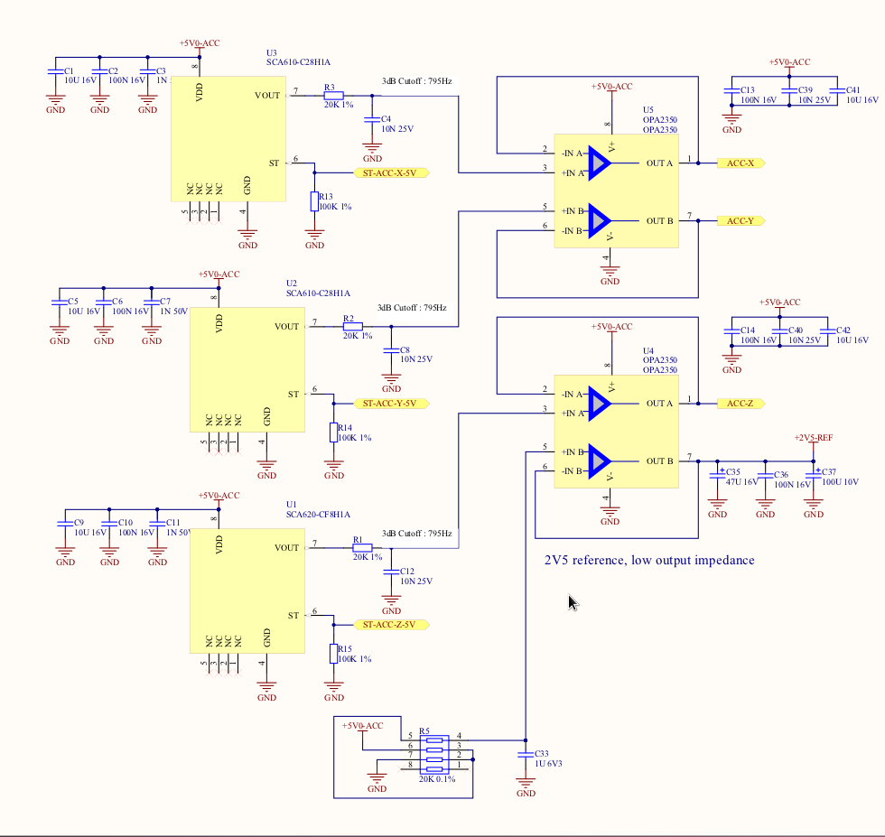
We have three single-ended sensors that are ratiometric to supply from 0-5V that we have interfaced to an ADS1256 via a OPA2350. The OPA2350 is configured as a unity gain voltage follower, and the sensor is connected to VIN+ via a simple first-order RC filter. The OPA350 directly drives AIN0 of the OPA2350 (not via a resistor or any other components). This is repeated for each sensor, connected to AIN4 and AIN6. Each is referenced to AINCOM, which is connected to the same 2.5V reference that drives VREFP. The 2.5V reference is buffered by its own OPA2350 as per the recommended circuit in Figure 26 of the ADS1256 datasheet.
Typically, one sensor is at about 4V and the others at 1.5V. On a scope, we can see the output of OPA350 of the 4V sensor dip by about 500mV for around 10ns and it takes around 20ns to fully settle (at least by eye). The power supply is stable during this time, as is the sensor output being fed into the op-amp. The other channels, and the voltage reference also dip, by around 100mV or so. Adding a capacitor (220N, low ESR/ESL ceramic) to the end of the OPA350 with the 4V signal reduces the dip to 100-200mV.
Is this normal and/or within acceptable limits? Or, am I better off redesigning the buffer stage with something like a THS4521 that has a much higher bandwidth to drive the ADC? Is there required to be a passive RC network (c.f. Figure 25 of the ADS1256 datasheet) that will help prevent the dip that I am observing on the scope?
-- Damien
(Note: I have a similar and potentially related question on the reference circuit itself: See http://e2e.ti.com/support/data_converters/precision_data_converters/f/73/t/218855.aspx)