This thread has been locked.

If you have a related question, please click the "Ask a related question" button in the top right corner. The newly created question will be automatically linked to this question.

ADS1299 Evaluation Module Setup

Other Parts Discussed in Thread: ADS1299

Hi,

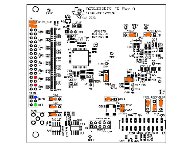
I am using the ADS1299 Evaluation Module, and am trying to figure out how to best set it up with an EEG cap for simple readings, blink test, etc.  

I am trying to figure out the simplest way to get things up and running with an existing EEG cap, and to be honest am having trouble making complete sense of the manual.  Can somebody suggest the quickest setup for pins to use, particularly for bias and reference, as well as the settings?  I've been playing around with them with so far minimal success.  I do have some experience with EEG data using NeuroScan hardware, etc.

Thanks.

  • Hi Greg,

    You might start by taking a look at Figure 60 on page 64 of theADS1299 Users Guide.  That schematic of J6 shows you how the inputs to the ADS1299, as well as the reference and bias nodes, are wired.  Is your EEG cap something you can provide us details (schematic/wiring diagram of the electrodes) on?

  • Hi Tom,

    Sorry, by Figure 60, do you mean the ADS1299EEG-FC Jumper Schematic?  Or am I looking in the wrong document?

    As for the cap, we haven't settled on a final cap, we're just trying to get a feeling for the inputs so far.  But for now, the cap we're using is a 64-channel NeuroScan cap linked to a pinout board that allows us to select up to 8 of its channels plus a bias and reference electrode.  Each of these are selected as single-ended inputs.

    I'm attaching a diagram of the evaluation board for the follow-up questions.  As an example, if I want to have two channels plus reference and ground/bias, I would plug the channels into the - pin of CH1 and CH2, as shown in red.

    Next attach a Reference electrode to the pin marked in green, then the Bias electrode to the pin marked in blue.

    We have jumpers on 1-2 of JP6, JP7, JP8.  Jumper on 2-3 of JP24.  Jumpers on 1-2 of JP18.  Jumper on JP19.  Jumpers on 1-2 of JP21, 2-3 of JP22, 1-2 of JP23.  Jumpers on 2-3 of JP2 and 1-2 of JP20.  Jumper on JP4.  These are marked in Orange.  

    In the software, on the Channel Registers tab, no settings were changed.

    On the LOFF and BIAS tab, all are left off.

    On the GPIO and OTHER Registers tab, SRB1 is changed to Closed (On) as suggested for single-ended inputs.  No other changes.

    Can you suggest anything else that should be done, or is this the correct approach overall?  I haven't been getting good / sometimes any signals except for a bit of noise with this approach, and I have gotten signals from the headset in the past.

    Thanks

  • Hi Greg,

    Yes - the input connector/jumper configuration on page 51 actually (not page 64 as I mentioned earlier).  What do you have applied to the (+) inputs of CH1 and CH2?

  • Hi Tom,

    I left the (+) inputs open / unconnected.

  • Is that the correct method?  Or should I be connecting something to them?  And should I be changing any of the settings within the software?

  • Hi Tom,

    I was wondering if there was some more information regarding these questions?

    In simple terms, if I'm connecting an EEG cap with included reference and bias electrodes, to which pins on the dev board should I be connecting them?  And should the jumpers be moved?  And is it alright to just connect them to the negative pins, and leave the positive pins unconnected?

    Thanks,

    Greg

  • Hi Greg,

    My appologies for the delay here - the ADS1299 has a differential input, so you need to have both the (+) and (-) terminals connected to 'something'; the positive pins (for instance) cannot simply de left to float.  Can you point us to a schematic or wiring diagram of the cap so that we can give you a bit more detail on how you might hook it up?

  • Hi Tom,

    I understood from the documentation that it was possible to connect a single-ended input, which is why I'm just wondering how to terminate the other end, even if it's just sending it to Ground or Reference.  

    We're using a NeuroScan EEG cap with 64 channels and selecting the channels that we want to use with a pinout board as seen here:

    The pins connect to individual electrodes, so it is a single-ended output, which we are connecting from this pinout board to the development board.

    Sorry if I'm missing something obvious in the documentation, and thanks for the assistance.

  • Also, can you verify a little bit more from section 4.6.2, in single ended inputs?

    1. Set all jumpers to factory defaults as described in (No section given?)

    3. Short pins 5 and 6 of JP6, set SRB1 in MISC1 register to route SRB1 pin to negative input of channels. (From the schematics, I only see 3 pins of JP6)

    4. Provide single-ended inputs to pins 36, 32, 28, 24, 20, 16, 12, 8 for channels 1-8 of J6.

    Is there anything that I am missing there?  Can you clarify these instructions further for single-ended inputs?

  • Hi Greg,

    Sorry for the long delay here - how is your project going?

  • Hi,

    I discovered the same problem. There is on page 17 in the user´s guide at point 4.6.2 Single Ended Inputs mentioned to short pin 5 and 6 of JP6. But JP6 has only 3 pins? Can somebody please explain how to Connect Single Ended EEG Signals and where to connect Patient GND and Reference. Which jumpers must be placed and what to do with unconnected inputs?

    Regards

  • As there is a Lack of Information from the TI-Team, i figured out, that there a plenty of wrong information in the User´s Guide. JP6 is, wrong, it should be pin 5-6 of JP25.

    But the Problem where connect the BIAS and REference Electrode is still not clear. Can anybody help?

  • Hi Melanie,

    Thanks for pointing out the mistake in the User's Guide. I will make a note to have it corrected.

    For Single-Ended inputs, the BIAS_ELEC (= (AVDD-AVSS) / 2) may be routed internally to the negative inputs of each channel. This is achieved by setting the SRB1 bit = 1 in the MISC1 register. Please refer to the MISC1 and Input Multiplexer sections of the ADS1299 datasheet.

    Thanks, hope this helps!

    Regards,

  • Hello Ryan,

    I thought I need the negative Input for the reference signal. Normally in EEG you have the electrodes and one reference electrode. You compare the EEG signals to one reference signal from the middle of the head. As shown in the picture. But what is the Bias signal for? Is it for the analog GND of the the chip?

    Regards,

    Melanie

  • Hi Melanie,

    Thanks for the explanation!

    Therefore, a single-ended measurement should use the REF_ELEC as the negative input to all of input channels. This can be done by routing REF_ELEC to the SRB1 pin and setting the appropriate registers in the ADS1299.

    Another alternative to route REF_ELEC to the negative channel inputs is to remove the jumper on (1-2) of JP25, and tie REF_ELEC to pin 1 only. Then, place a jumper on the appropriate pins of J6 (9-10, 13-14, 17-18, 21-22, 25-26, 29-30, 33-34). One advantage to doing this is to improve common-mode rejection as both the (+) and (-) inputs to each channel should see nearly the same input impedance to the ADS1299.

    For the BIAS_ELEC, the intention behind this feature is to drive patient to a known potential, similar to the way the bias potential known as "Right Leg Drive" sets the common-mode of the patient in an ECG application. The BIAS_ELEC is generated internally and set to mid-supply. JP25 on the ADS1299 EVM allows you to route this bias potential to the (+) inputs (shorting 3-4), or the (-) inputs (shorting 1-2). If (5-6) are shorted, this BIAS_ELEC is shorted to the REF_ELEC and fed back into SRB1 pin of the device.

    Since you are planning to use your own reference signal from the REF electrode in your diagram, you simply need to disconnect (5-6) on JP25, and connect your reference electrode in either of the two methods I described earlier.

    Do you plan to bias the patient as well?


    Regards,

  • Hi Ryan,

    normally we do not bias the patient, because of security reasons and DIN requirements.

    But I will think about this point.

    You helped me a lot with your explanation.

    Thank you.

  • Hello Ryan,

    As you described we can route REF_ELEC to the negative channels.

    The question is do we need to avoid R11?

    Or we need to simply short pins 1 and 6 on JP25?

    Best Regards

  • Hi George, 

    I do not see a reason to avoid or remove R11. I believe the intent behind R11 and C75 are to low-pass filter the reference (cuttoff freq at 6.786kHz).

    Where are you getting your REF_ELEC from and what is the expected value?

    If you want to apply the REF_ELEC voltage to your negative inputs, the two ways to do it as I described are through the SRB1 pin, or by shorting 1 and 6 on JP25 like you mentioned. To connect to SRB1, you could either buffer the reference through U4, or bypass it, depending on how you configure JP7 and JP8.

    Does that answer your question?

    Regards,

  • Hi Ryan,

    Thanks for a good answer.

    The REF_ELEC means NETconnected to the SRB1 with or without buffer U4.

    If we use a positive inputs AN1P- AN8P as single ended inputs we should connect all negative inputs to one net ((9-10) TO(33-34)).

    Then if we obtain a signal from head of the patient (CZ point)= COM_REF for (AN1P-AN8P) we need to connect to R11 at any scenario.

    Please correct me if something wrong.

    Best Regards