This thread has been locked.

If you have a related question, please click the "Ask a related question" button in the top right corner. The newly created question will be automatically linked to this question.

ADS1147 DRDY mode problem

Other Parts Discussed in Thread: ADS1147

Dear all,

We are developping an application in which we would like to connect an ADS1147 to an MCU using only pure SPI lines (SCK, DIN, DOUT, CS). We would like to synchronize the start of conversion and to be notified as soon as it is finished.

For that reason, we are configuring the ADS to use DOUT pin as DOUT/DRDY output and to disable the continuous conversion mode. Aparently the DRDY config works correctly when using continuous conversion mode. However, as soon as we stop the continous conversion mode, the DRDY pin does not fall down anymore after the start of the conversion.

Just for reference, we are using ADS1147 evaluation board where by default START & RESET pins are connected to Vcc.

The sequence that we are using is as follows:

> Configure Data output rate writting SYS0 register (WREG cmd).

> Enable DRDY_MODE by writting IDAC0 register (WREG cmd).

> Disable continuous conversion mode sending a SDATAC cmd.

> Send a SYNC cmd to start conversion.

> Wait for a falling edge on the DRDY pin.

Does anyone use this configuration? What are we doing wrong?

Best regards,

Roger.

  • Hi Roger,

    Welcome to the Forum!

    Controlling the ADC conversions:

    The ADS1147 is continuously converting when the START pin is set high.  In most applications the user will use the START pin to precisely control the conversions of the ADC.  The DOUT/DRDY will trigger low after the conversion is completed.  The device goes to sleep mode and stops conversions when the START pin is set low or when the SLEEP command is issued.  In your application, since you want to tie the START pin high and control the device only using the SPI,  if you need to stop conversions, a possible configuration may be to send the SLEEP command to stop the conversions.  The user will need to issue the WAKEUP command to restart the conversions.

    If you need to synchronize the device with other converters; the user could either control the START pin of the devices with the same GPIO or alternatively issue a SYNC command.

    RDATAC and SDATAC Modes:

    These commands control how the conversion data is updated on the output data register; however, they do not control the conversions.

    On RDATAC mode the user can read the conversion result by feeding SCLK's into the device after DRDY signal toggles low indicating a conversion is ready; Since the device is continuously updating conversion results to the output register, the user is required to monitor the DRDY signal and finish the conversion data read before the next falling edge of DRDY or corrupt results will occur.

    On SDATAC, the user is not always required to monitor DRDY; since the conversion results are updated to the output register while issuing the RDATA command.  However, the DRDY signal should still toggle low when conversions are ready.

    I would expect that you should still able to see the DRDY to toggle low when conversion is ready; however, since you are using the DOUT/DRDY; CS must be held low or DOUT/DRDY will tri-state. Is CS being held low while waiting for the DOUT/DRDY falling edge?

    Thank you and Best Regards,

    Luis         


  • Hi Luis,

    Thank you very much for your quick and complete description about how ADS1147 works.

    As in this application we would like to avoid using dedicated lines we must use SYNC command to start the conversions. To assure that DRDY signal will have a high value, we send always 2 NOPs before sending the SYNC command. This method allows us to check only the value of DRDY to detect the end of the conversion.

    After sending SYNC command we leave the CS in a low state as you said until a falling edge of DRDY signal appears. Afterward we use RDATA CMD to load the data in the output register and we send 2 NOPs to read the value.

    Thus, the complete reading sequence is: 2 NOPS + SYNC CMD+ Wait until DRDY falls down + RDATA CMD + 2 NOPS

    When RDATAC mode is used the DRDY signal falls down after aprox. 500us which match with the configured conversion rate (2000 sps). See following capture (CH1 = CS, CH3 = CLK, CH4 = SIN, CH2 = SOUT).

    However, if we set the SDATAC mode at the beginning and we exectute the same code, the DRDY does not fall down anymore. See following capture (CH1 = CS, CH3 = CLK, CH4 = SIN, CH2 = SOUT)

    Best regards,

    Roger.

  • Hi Roger,

    I went ahead and experimented/confirmed the sequence.  The DRDY dedicated pin toggles in both SDATAC mode or in RDATAC mode; however, you are correct, the DOUT/DRDY pin will not toggle when the conversion is ready on the SDATAC mode, since the output register is not loaded with new conversion results until the RDATA command is issued..  In your application, since you are not able to use dedicated lines for the DRDY pin or the START pin, you may need to run the device in RDATAC mode to know when the conversion results are ready and monitor the DOUT /DRDY.

    As you have  mentioned, in RDATAC mode after sending the SYNC command (and setting the DRDY MODE bit to 1); the DOUT/DRDY pin will toggle low indicating a conversion result is ready and you may send the 16 clk's NOP to read the conversion results.   In this application, are you planning to share the ADS1147 SPI bus with other devices? 

    Thank you and Best Regards,

    Luis


  • Hi Luis,

    Thanks for your testing. I thought we were doing something wrong.

    In our application we would like to connect at least two ADS1147 in the same SPI bus. The starting of both ADCs conversions must be synchronized.

    We plan to use SYNC cmd to start conversions however it is not clear to us how to detect the end of both ADC. Is it possible using DOUT/DRDY? I guess is not possible as it could lead to a bus line conflict. In other words...what should be the command sequence to execute and read two synchronized conversions using the same SPI bus (without additional lines)?

    If I understood correctly how ADS1147 works, the only way is doing something like that:

    1. Toggle low both CS (CS1, CS2)

    2. Send SYNC cmd

    3. Wait a fixed amount of time corresponding at least to the conversion time

    4. Toggle high CS2

    5. Read Data1

    6. Toggle high CS1 and Toggle low CS2

    7. Read Data2

    8. Toggle high CS2

    Is that correct?

    Best regards,

    Roger

  •  Hi Roger,

    The routine provided above should work on SDATAC mode where CS1 and CS2 is set low while issuing the SYNC command and the user waits a fixed delay as a function of the data rate.  In this case the user will need to account for the variation of the data rate of the devices which is a function of the master clock frequency.  The internal oscillator of the ADS1147 variation is typically in the order of +/-1% with a guaranteed maximum of +/-5%; and also will need to account for the microcontroller clock variation.  If the application requires exact synchronization, a high precision external crystal oscillator could be using driving the master clock CLK pin of both ADS1147 devices..

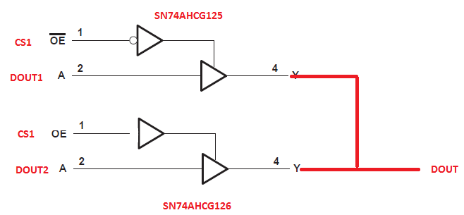
    If the application requires to know precisely when the conversion has ended and both devices share the SPI bus; a possible solution is to run the devices in RDATAC mode; driving the Master CLK pin with an external crystal clock oscillator and monitor the DOUT/DRDY of only one device.  The SYNC command will have to be issued while holding both CS1 and CS2 low.  In order to avoid a possible conflict on the DOUT1 and DOUT2 lines (since the devices are set up in RDATAC mode); the user could use external logic.  A possible solution is to use gated buffers controlled with one of the CS control lines.  The SN74AHCG125/G126 devices could be controlled with CS1; avoiding the conflict.

    Best Regards,

    Luis 

  • Hi Luis,

    At the end, we problaby will go with the waiting time solution as we would like to keep the hardware as simple as possible.

    It could be great if this kind of devices include a command to inquire the status of the conversion. Anyway, thanks for your support and advices on this matter.

    Best regards,

    Roger.