This thread has been locked.

If you have a related question, please click the "Ask a related question" button in the top right corner. The newly created question will be automatically linked to this question.

Bits Flip in MSC1210 Flash memory

Hi Experts,

I am right now facing the problem of bits flip in MSC1210 Flash and need your kind help on it. The detail of the issue is,

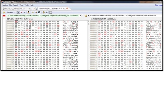
"We are using MSC1210 microcontroller in our high temperature downhole product for Oil field services. Recently we received 4 cases of our product failure  and these failure turned out to be caused by the microcontroller MSC1210(microcontroller stopped working/Stuck). For investigation purpose, we compared the firmware (hex) file downloaded (at the time of programming this micorcontroller) and the firmware (hex) file read-back (after failure) from the same micorcontroller. By right these 2 files should be same, but to our surprise, we found out that there are differences in the Code Flash memory contents at 2 address locations, which corresponds to 2 bytes, as shown in the table below Also please find in the attachment, the screenshot of the comparison of correct hex file data (on the left side, highlighted red) and corrupted hex file data  (on the right side, highlighted red)

Address Location

Correct Data Byte

Corrupted Data Byte

Remarks

0x0000

0x02 ( binary = 0000 0010)

0x00 (binary = 0000 0000)

2nd data bit (from right) is flipped from 1 to 0

0x0080

0xB4 (binary = 1011 0100)

0x80 (binary = 1000 0000)

3rd, 5th and 6th bits (from right) is flipped from 1 to 0

Importantly, the flash memory is programmed as write – protected (with default HCR0.PML = 1). All of 4 product were failed at low temperature (not even exposed to high temperature).

Questions:

1) Did anyone here ever received this kind of complain? If yes, then how you overcome this issue? If no, then please suggest a solution for the problem explained above.

2) I am interested to know, why is this happened and what could be the possible root causes and how could it be avoided?

Any help on this issue will be highly appreicated. Looking forward for the kind help.

Regards

Asad

  • Asad,

    On a couple of instances we have heard about flash corruption issues.  However this has been very rare.  What may be the problem is a transient voltage either on the supply or inputs.

    Do all four failures have flash corruptions?  And if so, are there any common memory locations?

    Best regards,

    Bob B

  • Bob,

    Thanks for your kind help.

    We starterd looking at the possibility of transient voltage from supply. And as per your query, we did the investigation on 1 of the failure. We are going to start the same investigation on the second failure. While for rest of the 2, we destryoed the evidence by re-programming the Flash (And after re-programming, the micorocontroller starts working perfectly...strange to me..!)

    Well, all of these 4 failure have same symptoms, that their microcontrollers were working perfectly and all of the sudden , the microcontroller stopped working (with no external failure). I will be able to update you, that whether there is any common memory location failure or not, once I am done with the investigation on the 2nd failure.

    I really appreciate your help.

    Thanks

    Asad


  •  


    Hi Bob,

    Reference to previous reply, I have completed the failure investigation on another flash. This flash seems to have 26 bytes corrupted. Interestingly, all bits flip happened from 1 to 0, as shown below in the screen shot. This screen shot is from the hex file comparison between the programmed hex file (right) and the corrupted read-back hex file (left).

    As per your query, both flash failures have data corruption at the start up address locations (0x0000 - 0x013A) only, though not all the corrupted address locations are same in the 2 flash failure cases.

    Could you please share with us, which event is actually causing this error and how could it be avoided?

    Regards

    Asad.

  • Hi Asad,

    Generally you need to protect the MSC1210 from events that push the device past the specifications in the Absolute Maximum table of the datasheet.  This happens quite often from ESD/EMI/RFI events, but can also happen if there is overvoltage applied to the inputs.  The internal ESD protection diodes will conduct at about 300mV above the supply, and then the overvoltage will be applied internally to the device.  It is best to apply some sort of suppression or protection external to the device.  This can be done through EMI/RFI filter techniques, and/or Schottky diodes or TVS diodes.  Layout is also critical to minimize noise pickup.

    One area that is often overlooked is the AGND and DGND ground connections.  There needs to be a low impedance path between the ground connections of the MSC1210.  Adding additional impedance (like a ferrite or choke) can cause issues of seperating the grounds by a significant amount due to transients.

    Best regards,

    Bob B

  • Ho Bob,

    Thanks for your kind guidance.

    Well we are also suspecting the transients issue in power supplies which has some start-up noise . We have already started closely monitoring the VCC and the transients in it.

    On other note, we are using TI downloader for programming MSC1210. TI downloader takes care of flash erase/write operation while programming. Could there be any possibility that TI downlaoder failed to give enough time for write cycle (30us to 40 us) and erase cycle (4ms to 11ms) which corrupted the bytes?

    Regards

    Asad


  • Asad,

    The TI Downloader program calls the MSC1210 boot rom routines, so I don't really think there should be any issues with the timing using that program.  The program establishes the timing relative to the baud rate and crystal clock frequency used.

    As some further information, an erase sets the flash bit values to 1, and a write of 0 sets the bit to 0.  A write of 1 is ignored and has no effect.  When you erase the flash, it should set all the bits to 1.

    Some further information can be found in the following document regarding flash endurance:

    ftp://ftp.ti.com/pub/data_acquisition/MSC_CD-ROM/Application_Notes/sbaa091_Maximizing_Endurance_of_MSC1210_Flash_Memory.pdf

    Best regards,

    Bob B