This thread has been locked.

If you have a related question, please click the "Ask a related question" button in the top right corner. The newly created question will be automatically linked to this question.

ADC16V130, Input impedance

Other Parts Discussed in Thread: ADC16V130, ADC16DV160

What is the input impedance of the ADC16V130 in the frequency range of 50MHz to 150MHz?

I know that the input is a switched capacitor arrangement. The data sheet show the switches and the two capacitors, Cs, but no values are specified.

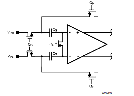
I need to know how to model the input so that I can assure that the impedance seen by my band pass filter is as near 50 ohms as possible.

Thank you for your time,

Larry Stanton

Senior Engineer, Product Development

HARRIS Corporation

Broadcast Communications Division

Pacific Design Center

1493 Poinsettia avenue, Suite 143

Vista, CA USA 92081

lstant01@harris.com

(760) 936-4018

  • Larry,

    The input sampling cap for the ADC16V130 is 6pF on each side to AC GND. About 1pF more must be added for parasitics. I have also attached the single-ended S11 (during sampling phase) for the ADC16DV160 which has the same input network as the V130.

    Regards,

    Josh

    3618.ADC16Dv160_S11.zip

  • Joshua,

    Thank you for your response. I extracted the file and ended up with ADC16Dv160S11.S1P. I opened the file in MS PowerPoint. It appears that each page is an entry from and HP8714. I assume that the left most number is the frequency in MHz, the middle number is Real part of the normalized impedance and the right number is the Imaginary part of the normalized impedance (reference Impedance = 50 ohm).

    These numbers do not seem to match the S11 numbers derived from the Smith chart on page 21 of the ADC16DV160 data sheet. For example, from the .S1P file @500MHz the value is 0.07432335 - j0.6948786. From the Smith chart of the Data Sheet, the value appears to be 0.4 - j1

    Please tell me how to interpret the numbers.

    Thank you,

    Larry S.

  • Joshua,

    I found my error. I see that I have to calculate the impedance with the equation z = z0*(1+S)/(1-S). I made an EXCEL spreadsheet to do the calculations from S11 to impedance.

    I still need to run the numbers.

    Thank you,

    Larry S.

  • Joshuna,
    I am using adc16v130 in my design. I want to match my bandpass filter output impedance to adc input impedance. In my design ADC input is differential. The given measured S11 file is for differential input signal or single ended signal ?

    Regards,
    Dhaval Patel
  • Dhaval,
    It is single-ended
    Regards, Josh