This thread has been locked.

If you have a related question, please click the "Ask a related question" button in the top right corner. The newly created question will be automatically linked to this question.

ADS1298 Single Lead

Other Parts Discussed in Thread: ADS1299

Hello,

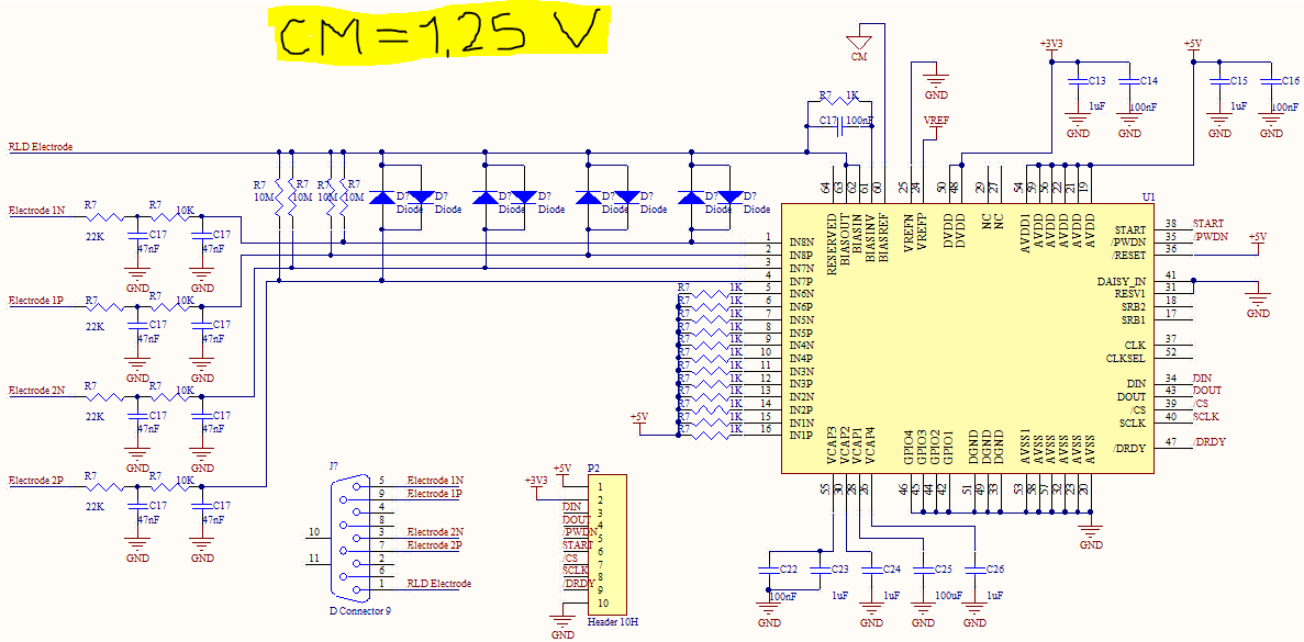
I also have a doubt about this...I am using an ADS1298 to implement an AFE for sEMG acquisition. Since I only intend to monitor 1 muscle, I am using only Ch1, so my question is: should I short circuit the other input channels I am not using, or this isn't necessary?

Thanks in advance!

  • Hello Marcia,

    I'm also developing a surface EMG application, i'm using ADS1299 and also have some doubts on how to connect it. But something I already solve is what to do with unused pins, you should connect them to AVDD as said in the FAQ section of this forum, take a look.

    For the AFE I'm developing I need to sense the biopotential of two muscles, that is 5 electrodes including the Bias Drive (or RLD), I have a lot of confusions on how to interface them to the ADS129x chip, since the datasheet isn't really clear about this and there is a lot of different proposals on how to do it, I'm also haven't received a direct answer of this query in this same forum, so i'm asking you back. If you already solve this, how you did it?

    I hope this answer help you out as I hope someone clarifies mines.

    Regards,

    Julián Grisales

  • Hello Julian,

    Thanks for your reply, in fact I had read the datasheet but ive overseen this detail...

    About the interfacing of the electrodes to the input channels, I followed the specifications in the datasheet and in the application notes. I attached below two screenshots of the schematic of my circuit, so that you can see how I did it. This schematic was designed to acquire signals from two muscles. The tag V_SHLD in the RLD circuit refers to an external shield connector of my EMG setting. For the diodes in the inputs, I intend yo use BAS40XY, meaning you can use oine package per channel. If you have any further doubts, please feel free to ask.

    Best regards,

    Marcia

  • Thank you very much Marcia, I'm using a unipolar configuration and I think this interface issue should change a bit of yours, but this very helpful though. I already did another post with this one and some other questions that could maybe help you or if you already solved them you could help me and the community. 

    Have a great day! :)

  • Hi Marcia,

    Looking at your design I notice that you use a 2nd order RC filter at the inputs, those values you selected are the sames values showed in the RLD datasheet, but the cut-off frecuency of this filter is close to the 135 Hz, witch is appropriated for a ECG application, you should consider using another filter according to the frecuency range of your sEMG application. Take a look on this:

    http://e2e.ti.com/support/data_converters/precision_data_converters/w/design_notes/the-ecg-and-eeg-frequency-range.aspx

    I'm also not using those clamp diodes as patient protection, instead i'm using an anti-parallel diode configuration between each input and the reference electrode. As show in the next image:

    This is my overall configuration without the reference and power circuits. As a second intention I'm telling you this to ask you how great is your advance in your project design. Have you passed to a testing stage? Any suggestions?

    That last question is also intentionally directed to those who has the greater experience using this family of devices (ADS129x). I would really be very thankful with any suggestion!

    Good day!

  • Hi Julian,

    it is prabably a bit too late to reply now, but I havent been working on this project since January. However, someone else tested the system assembled using the final schematics shown in the picture below, and they worked fine. 

    The hting you mentioned about the cutoff frequency makes sense and you are probably right, I guess I should have used a larger cutoff frequency, however, the puspose of the project was to evaluate slow walking movements, so I guess in the end it wasnt a big problem. The noise present in the system was filtered by post processing so the cutoff frequencies were not a big concern. The interest was to see if the circuit design worked, but i dont know how the SNR ratio was because i did not test it personally. Note that I used schottky diodes and small package components.

    I realise there may be better configurations, and I wonder if your antiparallel setting had better results. I dont have further suggestions but good luck in that :)

    Best regards,

    Márcia

  • Hi Marcia,

    Indeed it is a little late, but still very welcome. I also implemented my design with a few little modifications, it is working perfectly, even though i'm sensing signals with extremely little amplitude (<= 1mV). In case you're wondering the project was aimed to detect subvocal speech.

    I'm glad we could advance in our projects helping each other through this community, shared resources always works for better.

    Best regards,

    Julián.

  • Hi Julián,

    Yes indeed I have to thank you for your valuable suggestions and I am also very glad that you could manage to get the thing working in the end! :)

    I wish I could have helped more but still I hope this will help someone else in the future.

    Best wishes and keep up the good work,

    Márcia

  • you made subvocal speech with ads1299.

    I too want to do the same.

    Can you please tell me what was the gain set by you for PGA.

    how you converted the pulse signal to voice by making an application of windows or by any other method.

    I am interested in using ads1299+MMB0 for y project.

    Also if you can please inform me about the accuracy of your project.

    thanks in advance

  • Hello Julián,

    Can you share which modifications you've made to the circuit?

    Thanks in advance,

    Cecil