This thread has been locked.

If you have a related question, please click the "Ask a related question" button in the top right corner. The newly created question will be automatically linked to this question.

Reading internal temperature sensor value of ADS1118

Other Parts Discussed in Thread: ADS1118

Hi,

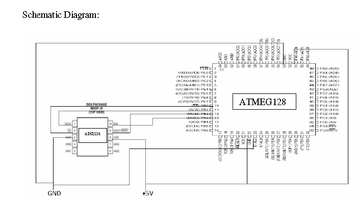
I am trying to read the internal temperature sensor value of ADS1118. It is interfaced with ATmega128 microcontroller using spi interface. The pin connection is ,

ADS1118                   Atmega128

CS            ---->             SS

DIN          ---->              MOSI

DOUT     ----->              MISO

SCK         ------>           SCK

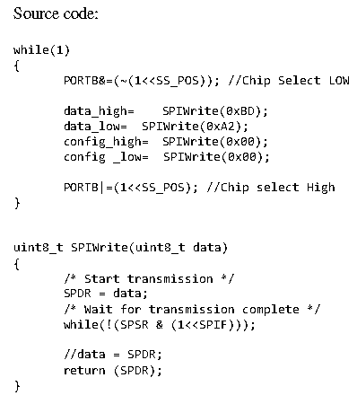
I am using the following coding,

PORTB &=(~(1<<SS));

SPI_WRITE(0xBD);

SPI_WRITE(0x92);

SPI_WRITE(0x00);

SPI_WRITE(0x00);

PORTB |=(1<<SS);

delay_ms(10);

PORTB &=(~(1<<SS));

data_MSB = SPI_READ(0x00);

data_LSB = SPI_READ(0x00);

config_MSB =SPI_READ(0x00);

config_LSB =SPI_READ(0x00);

PORTB |=(1<<SS);

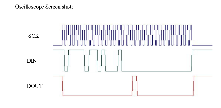
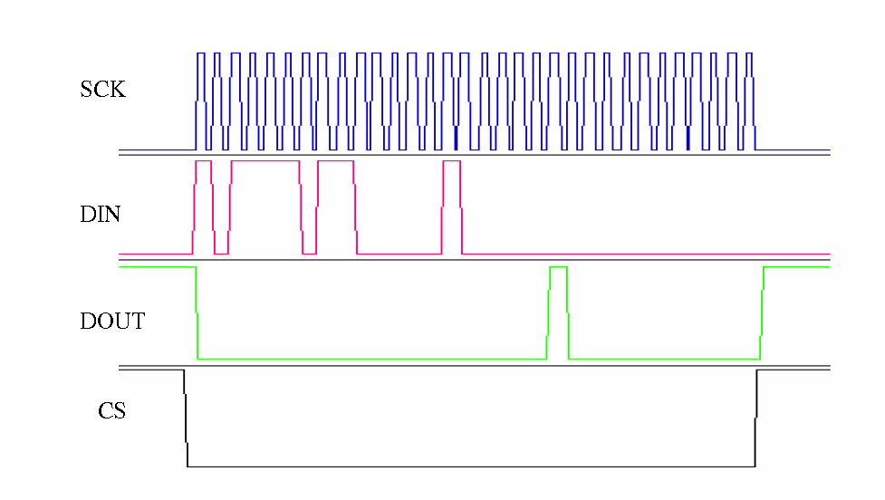
The problem is my DOUT pin is always in high state. DIN pin shows the correct value which is send. But i am not gettting any valid output from the IC. Please kindly help me.

  • Navaneetha,

    I see we have 2 posts running and I missed this one earlier.  The SPI is full duplex, which means you read and write at the same time.  In other words, you don't do a write sequence then a read sequence.  If you don't want to change the configuration, you write a NOP.

    Best regards,

    Bob B

  • Dear Bob,

    Thanks for your reply,

    I am running the microcontroller in 1mhz speed. And the SPI speed is fclk/128.

    I also tried the following code,

    PORTB &=(~(1<<SS));

    data_MSB = SPI_READ(0xBD);

    data_LSB = SPI_READ(0x92);

    config_MSB =SPI_READ(0x00);

    config_LSB =SPI_READ(0x00);

    PORTB |=(1<<SS);

    Still my DOUT pin is in high state. Can you tell me the procedure for read the internal temperature sensor value of ADS1118. And also give me any sample code if you have (for interfacing ADS1118 with atmel microcontroller). Thanks in advance.

  • Navaneetha,

    You can try forcing the device into continuous conversion mode by changing to 0x82 instead of 0x92.  SCLK should dwell low.  A scope shot would be helpful of the communication for verification.  Can you send me your schematic?

    I do not have Atmel code, but I can send you something for MSP430 if you are interested.

    Best regards,

    Bob B

  •  yes please send the code for MSP430. Meanwhile i will send you the scope shot and also the scematic.

  • Hi BOB,

    I am sending you all the information which u asked, I have also tried a pull up resistor with SCK and DIN but i got the same result.I am running the microcontroller in 1Mhz speed. And the SPI speed is fclk/128.

    connections:

    ADS1118                   Atmega128

    CS            ---->             SS

    DIN          ---->              MOSI

    DOUT     ----->              MISO

    SCK         ------>           SCK

    kindly tell me what going wrong.

    kindly let me know for further clarification.

    Regards,

    Navaneethan.

  • Hi Navaneethan,

    I will make an assumption as your description is in conflict with the schematic.  The assumption is you drew the schematic incorrectly based on the scope plots.  One thing not shown in the scope shots is the CS line.  I will again make an assumption that it remains low throughout the entire communication transaction.

    From the scope shots it appears your communication is on the wrong phase.  The data should change on the rising edge of SCLK and not the falling edge.  See Figure 1 of the datasheet.  The ADS1118 latches the data on the falling edge of SCLK, so if the data is not stable you will not communicate correctly.

    Best regards,

    Bob B

  • Hi Bob, 

    Thanks for your reply.

    Yes i made mistake while drawing schematic. The connection description is correct. CS pin is low throughout the communication as you can see it in the source code.

    I will check the SPI phase and update you. Is there any thing else i am missing in communication?

    Regards

    Navaneethan

  • Hi BOB,

    I tried SPI mode1 but still i am getting the same result. I also tried CS low completely and also for different configuration but i am getting the same result.

    kindly let me know what is going wrong. please tell me how to test ADS1118 is wroking or not?

    Regards

    Navaneethan.

  • HI BOB,

    Please tell me is there any way to check the ADS1118 is active or not???

  • Navaneetha,

    I've already told you how you determine whether your device is working.  You need to properly communicate with the device.  If you configure the device to continuous mode instead of single-shot power down mode this will help.  Please send me new scope pictures showing the changes you made to the communication, and I will re-evaluate the communication.  From the previous scope pictures it appeared the ADS1118 is working...just the communication is improper. 

    If you send the complete transaction (32 clocks) after the last clock you should see DOUT goes high.  In your previous post the scope shot shows that it does.  I can assume that your device is working.

    You probably don't want to keep CS low, as CS can reset the SPI bus if there is a communication transfer issue. 

    Best regards,

    Bob B

  • Navaneetha,

    It appears that your clock is in the correct phase now.  The scope pictures show the data written to the config register is 0xBD82 and not 0xBDA2 as you showed in the code snippet.  Try writing 0xBC92 instead.  This should start a conversion, go to temp sensor mode, and run continuously.

    What I don't understand is why you don't see the default configuration.  The configuration is returning 0x0800.  Also, make sure you have good ground and power connections between the micro and the ADS1118.  Do you have a bypass cap between the ADS1118 DVDD and ground?  Is it possible for you to send me a picture of your testing setup?

    Best regards,

    Bob B

  • Hi BOB,

    I need your help. Now my ADS1118 is working fine. The problem I am facing is when my thermocouple values goes in negative, it is not getting subtracted  from the room temperature (reference temperature) instead it is getting added. But for positive values it is working fine.

    For negative values i am taking the two's complement. After taking two's compliment  the milliVolt value is changing from negative to positive. Kindly help me in calculating two's compliment for negative values.

    Thanks 

    Navaneethan.

  • Hi Navaneetha,

    Maybe you can send me your code snippet of conversion and CJC adjustment.  If you use a short int type (2 bytes) you should be able to save your data without any conversion.  This works because the output of the ADS1118 is binary two's complement and will be formatted correctly from the start.

    Best regards,

    Bob B

  • hi BOB,

    I am sending the code. Please kindly have a look and let me know where i am committing error.After twos's compiment i am not getting negative values. kiindly help me.

    //Code snippet.

        int16_t   res;
        uint8_t   data_high,data_low;


        float    Res_val;

        float    refTemp;

        float twoCOMP;

    while(1)

    {

            PORTB&=(~(1<<CS1));

            data_high=    SPIWrite(0x00);
            data_low=  SPIWrite(0x00);
            if(step==0)
            {
                        SPIWrite(0x08);
                        SPIWrite(0xA2);

                         res=(data_high<<8)|data_low;
                         res = res>>2;
                         Res_val=res * 0.03125;
                         refTemp = Res_val;
             }

             else if(step ==1)
             {

                       SPIWrite(0xBC);
                       SPIWrite(0xB2);

                       res=(data_high<<8)|data_low;

                       //Calculating two's compliment for negative values
                       twoCOMP =(res>0x7fff)?res-(0xffff+1):res;


                       Res_val=( twoCOMP * (512/32768.0));

                      //Using this Res_val i will calculate the corressponding temperature value from the Ktype lookup table and assign the value to result variable

                      //Now i add the reftemp and result. This is my final result.

                      result = result +refTemp;

              }

              if(step==0)
                  step=1;
              else
                  step=0;

              PORTB |=(1<<CS1);

              _delay_ms(5);

    }

    Regards

    Navaneethan.

  • Navaneethan,

    As I stated in my last post, you do not need to convert the number to binary two's complement as it is already in the correct format.  So if the number is a negative value, it should remain that way.  I'm not exactly sure how your compiler is interpreting your formula but it appears wrong.  You are trying to subtract a number that is larger than the variable.

    I think you should be able to simplify and make:

    Res_val = ( (float) res * (512/32768.0));

    Best regards,

    Bob B


  • hi BOB,

    Res_val = ( (float) res * (512/32768.0));

    If i apply this formula what is the Res_val? and res?  should I get when the connector is open (ie., when i dont plug in the thermocouple).

    Now I am getting,

    Res_val = -0.015625

    res = -1

    but I am excepting

    Res_val = -511.9

    res = -32767

    because somewhere in datasheet i found when connectors are open the ADS1118 will give negative FS value. Normally in thermocouple measurement when the connectors are open we get -270 C (ie., Negative full scale).

    Please clarrify me in this data conversion.

    Thanks & regards

    Navaneethan.

  • Navanetha,

    Floating inputs can float to any level.  The input structure is a switched capacitor.  If the res value is -1, then the differential input is measuring close to zero.  If your inputs have pull-up and pull-down resistors on the differential analog inputs, then you can get an expected result with TC removed.  For example if you use resistors in the range of 1 to 10 Meg ohms, and you place a pull-up resistor on the AIN+ input to the supply, and another equally sized resistor on the AIN- input to ground, then with the TC removed from the input the reading result will be positive full-scale.  With the TC connected, then the resistors will bias the circuit so that the common mode will be at mid-supply and the measurement will still be the difference of the AIN+/AIN- inputs.

    If you want to see if the calculations are working correctly, swap the TC connections and you should see a result close to the original but with inverted sign.  It may not be the exact same value as there may be some differences relative to offset.

    Best regards,
    Bob B

  • Hi BOB,

    How are you?..Hope you are doing good..

    Now my ADS1118 is working fine. One problem with the IC is the value which i am getting is oscillating bettween 2 degrees range. Is there any way to stop this oscillation other than taking average of the samples. I require any hardware which could reduce this oscillation. Kindly help me in this regards..

    Regards,

    Navaneethan.

  • Hi Navaneethan,

    Are you seeing this value change with the internal temperature sensor?  What data rate are you using?  The change in value could be due to noise, or it could be related to the conversion threshold between each LSB.  If it is on the edge of transition it may toggle between codes.  Slowing the data rate may help reduce the conversion noise.  This would have a similar effect as averaging.

    Best regards,

    Bob B

  • Hi BOB,

    Thanks a lot for ur support,

    The internal temperature sensor value is stable. The data rate which i am using is 250 sps. Now i slowed it to 64 sps. Now the value seems to be stable. I am using PGA setting as +/- 0.256 V. I will calibrate the device and come back to u if i face any problem.

    Thanks again,

    Regards

    Navaneethan.