This thread has been locked.

If you have a related question, please click the "Ask a related question" button in the top right corner. The newly created question will be automatically linked to this question.

need some help on using MSP430 as ADC

Other Parts Discussed in Thread: THS1206, MSP430G2553

I have an MSP430 launchpad (MSP-EXP430G2 Rev 1.4). I have M430G2553 Ic in it.

I need to use this as an ADC, where i'll be providing an input signal( in the range 0.1-0.2V ) . i had read thru some of the example codes but wasn't able to figure the connection . .Can anyone help me in making the connections and also suggesting me the  appropriate code ??

  • Hi Kiran,

    I see you posted the same question in the MSP430 forum - that is the proper forum for questions regarding the embedded ADC of the MSP430 processors.  Just curious here, but were you going to try and use the THS1206 with this launchpad?

  • Hi Tom Hendrick,

    Thanks for the information. I had thought of using the ths1206 with the launchpad . The reason for this is that Iam finding difficulty in programming the MSP430g2 launchpad for the ADC  . I would like to seek your help in this regard .

    thanks.

  • Hi Kiran,

    From the THS1206 side of things, getting it to talk with an MSP430G2553 might be possible, but it really wants to be used with a processor that has a proper parallel interface.  The MSP430 team should be able to help you with their embedded ADC.

  • Hi  Tom Hendrick,

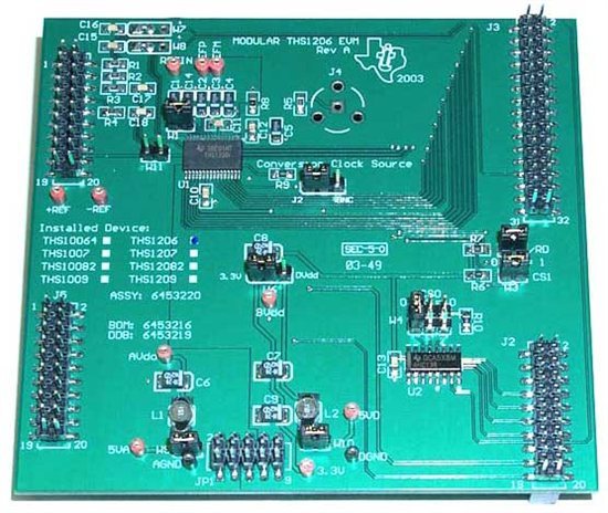
    Could you help me in this  THS1206 evm- :

    Iam providing an analog input of 0.1 -0.2v to AINP and GND to obtain its digital form using THS1206EVM . .But i am not able to obtain the outputs. I also have few doubts which are described below-

    Is the pin Avdd,Dvdd,Bvdd ,to be connected to power supply?What is the ideal supply votage to be given ?

    Where should i apply the reference voltage , i.e, at +ref & -ref or at refp & refm ?

    What about the connections to the pin - 5VA ,5VD,3.3V,REFIN ? are those pins to be left open ?

    And in the j1 the unused odd pins are to be grounded externally or are they grounded internally?

    If possible could you mark the pins in this image ?