This thread has been locked.

If you have a related question, please click the "Ask a related question" button in the top right corner. The newly created question will be automatically linked to this question.

ADS1282 connected to nanovolt amplifier A22

Other Parts Discussed in Thread: ADS1282, OPA1632, INA128, ADS1246, ADS1259

Hello,

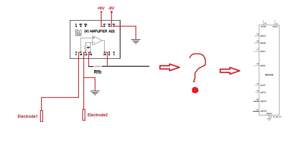
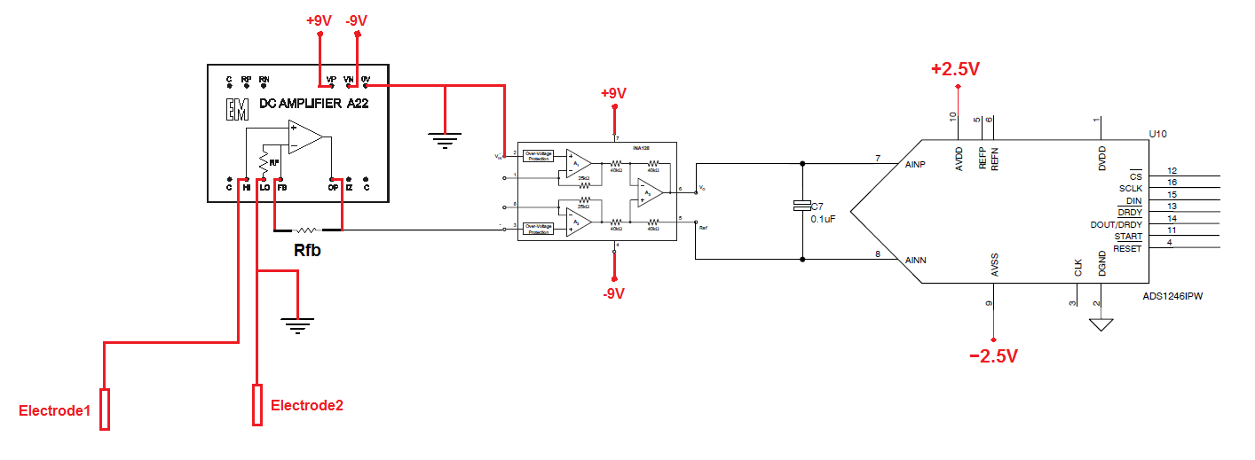
I want to connect the nanovolt amplifier A22 to the ADS1282. (http://www.emelectronics.co.uk/spec/A22.html)

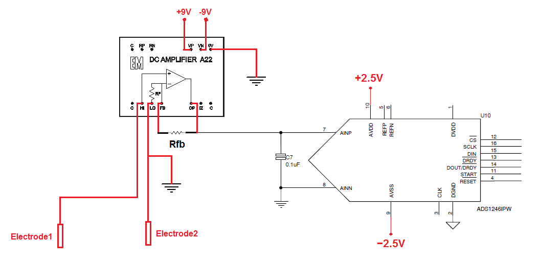
The amplifier is dimensioned by Rfb, so that the maximum output voltage is + /-2.5V.

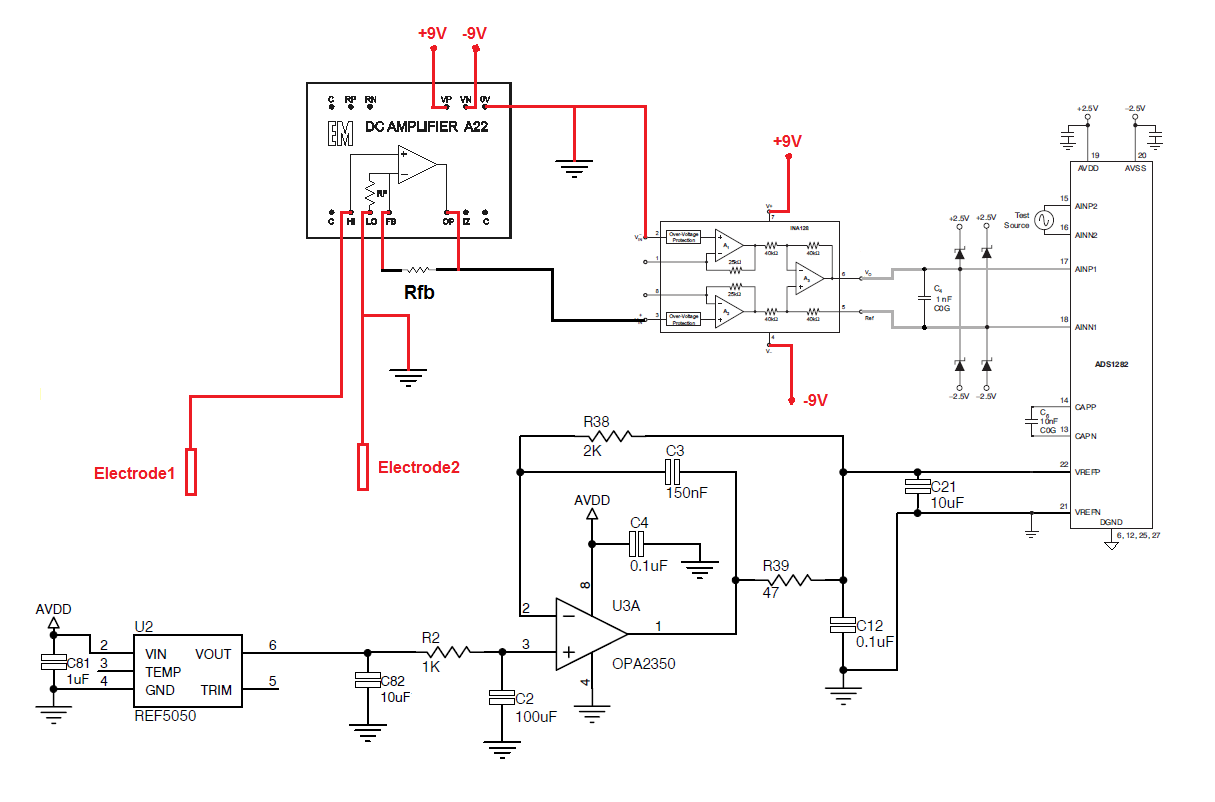
I want to know if the schematic below is well dimensioned or not! That is, AVDD=2.5V, AVSS=-2.5V, AINP1=AmpOutput, AINN1=GND, VREFP=2.5V and VREFP=GND, is OK or not?


There is another possible schematic better than this?


Best regards

Ivo Bernardo

  • Hi Ivo,

    The ADS1282 has an interal PGA with an input operating range of AVSS + 0.7V < AINN or AINP < AVDD - 1.25V (see page 14 in the datasheet). The input signal level and common-mode voltages should therefore be held between 1.25V and -1.8V. Also, with a 2.5V reference voltage (and PGA with a gain of 1)  you can only have a +/- 1.25V differential input signal. Therefore, reducing the gain by a factor 2 will make sure the that input signal does not cause the PGA output to clip and add distortion to the measurement.

    If I may ask, what you are measuring with the electrodes? If you were able to keep the input signal a differential signal, you would have twice the dynamic range.

    Regards,
    Chris 

  • Hello Chris, thank you for your support


    This circuit is for measuring difference of potential  in the soil of the seabed

    In my circuit, if I change the reference voltage for REF5050, is that correct?

    Relative to the rest of the tensions and GNDS, they are correct?


    Best regards,

    IB

  • Hi Ivo,

    Cool application! Changing the reference voltage to 5V solves the one problem of exceeding the full-scale range code. However, the remaining issue is that the ADS1282's PGA input range is still limited to:

    AVSS + 0.7V < AINN or AINP < AVDD - 1.25V
    or
    -1.8V < AINN or AINP < +1.25V

    By using a single-ended input voltage, your input is limited to +1.25V to -1.8V; where as a differential input voltage could swing +/-2.5V with a common-mode voltage of 0V (each voltage input would be +/-1.25V when referenced to ground, but would appear to be +/- 2.5V differentially). Therefore, you need to limit your input to at least +/-1.25V and then use the internal PGA to gain up your signal to either +/-1.25V or +/-2.5V internally, depending on what reference voltage you decide to go with.

    In summary, your application with a single-ended input must use a PGA gain of at least 2 (V/V) to take advantage of the full dynamic range of the ADS1282. However, the voltage output of the A22 will need to scale-down as you increase the PGA gain.

    Regards,
    Chris

  • Thanks Chris, for your help!

    Now I understand what you mean. Therefore, I prefer to make the same assembly as the ADS1282EVM with differential amplifier OPA1632.

    I want to know if the resistor R12, the amplifier input, is it really necessary?


    Best Regards,

    IB 

  • Hi Ivo,

    I believe that resistor was placed there to provide a path for the input bias current when no input was connected to the EVM. So, no it is not necesary, though you may want to consider how to prevent these inputs from floating during power up or in event cases, such as if your sensor is not connected or if it malfunctions.

    What type of performance is most important to your application? The OPA1632 is flavored towards audio (or AC) applications and therefore has very low noise and distortion. If you're measuring a pre-dominately DC signal though, you may be more interested in the offset and drift performance of the amplifier. (White noise is less crucial because you can use a filter with a lower cutoff frequency to greatly reduce the noise bandwidth. It is the 1/f noise, or drift, that dominates at lower frequencies).

    Regards,
    Chris

  • Hello Chris, thanks again for your support!

    You are absolutely right about the importance of drift and offset in this application! This application is to measure the difference of potential (in 2 points) on the seabed, should not be much high frequency noise, because it must be filtered through the water layer.

    If you can forget all my schematics, in your opinion, what is the best schematic that you can do?

    Best regards,

    IB 

  • Hello,

    I think it is better to use a Differnz Amplifer (INA128) or better a Differnez OP Amp with Differenz output.

    I use the INA128 and a low pass filter .

    Thanks Bernd

  • Thanks for that Bernd!

    I agree that is a good potential option. 

    You must have some kind of target performance/power/price in mind that lead you to implement the A22. That's not a problem, but what are your design requirements? You can take the approach I suggested above and still manage to use the full input range of the ADS1282 with the A22. However, having a differential input would allow your input signal to be twice as large, consequently (assuming noise remains the same) your SNR would increase by 6dB.

    What sampling rate and ENOB are you wanting to achieve?

    Regards,
    Chris

  • Hello Bernd and Chritopher,

    I want to use the amp a22, because I want to measure signals in the order of nanovolts. The sampling rate of the signal is 1SPS.
    Regarding my circuit voltage reference is correct or do I have to do the same as the ADS1282EVM? The rest of the circuit is correct too?

    Best regards

    IB


  • Hello all,

    i want to use to full rate of 4Khz, but my other system is not able to store the data as quickly.

    Have anyone a idea ?.

    The system must work outside with very low power for one or two weeks.

    The data store are gigabytes. ( 4000Hz * 2 Ch * 8Bytes* 60Sek * 60Min *24h * 14 Days)......:-(

    Bernd

  • Hello Bernd and Chritopher,


    Replacing the ADS1282 by the ADS1246, now I can use "single-ended input" with a maximum input of + /-2.5V, right? For that I have to put AVDD=+2.5V and AVSS=-2.5V.

    In relation of the Voltage Reference Input (VREFP and VREFN), I have to copy the same circuit as the ADS1248EVM?


    Best regards,

    IB

  • Ivo,

    You can use the ADS1246 but keep in mind that the internal PGA will have an input-common-mode voltage range that will limit your input signal range.

    You may want to look at the ADS1259 as well. It does not have an internal PGA and it has lower input-refered noise.

    Regards,
    Chris

  • Hello Chris,

    I wanted to use because the ADS1246 has a PGA, and so I can have better resolution for smaller signs.

    I don’t understand what you mean with "Internal PGA will have an input-common-mode voltage range that will limit your input signal range" You mean that I can’t measure signals + /-2.5V, using single-ended input?

    And if I use a ADS1246, combined with an INA128 improves anything?

    In relation of the Voltage Reference Input (VREFP and VREFN), I have to copy the same circuit as the ADS1248EVM?


    Best regards

    IB

  • Hi Ivo,

    You can measure a +/-2.5V differential signal; For single-ended signals with the ADS1246 you are limited to about +/-2.3V. Let me explain...

    The ADS1246 still views your single-ended input signal as a differential voltage. It also sees a common-mode voltage which is the average voltage applied to both inputs, for example when you apply a 2.5V single-ended singal (a differential signal between 2.5V and 0V), the common-mode voltage is (0V + 2.5V)/2 = 1.25V. Most analog devices like to have the common-mode voltage centered at mid-supply. With +/-2.5V supplies, the desired common-mode voltage, or mid-supply, is 0V.

    The common-input voltage range of the ADS1246 is limited to +/- 1.15V (go to this link for an explanation of how I calculated this: http://e2e.ti.com/support/data_converters/precision_data_converters/w/design_notes/1370.input-voltage-range-requirements-for-the-ads1248-and-ads1148-families.aspx)

    Therefore, a single-ended input, referenced to 0V, can only swing +/- (2*1.15V) or +/-2.3V and be within the allowed common-mode voltage range. Exceeding this will not allow the PGA to function properly (in its linear region) because it requires some voltage "headroom".

    Does that explaination make sense?

    You do not have to copy the voltage reference as seen on the ADS1248EVM. That circuit uses the REF5020 which is only a 2V reference and you will most likely need at least a 2.5V reference.

    Regards,
    Chris


  • Hello Chritopher,

    Thanks for all support that you have given me, has been very helpful!

    If I use the INA128 amplifier solves this problem?

    If the problem is not resolved, I will have to limit the A22 amplifier so that the maximum voltage is + /-2.3V.


    Thanks

    IB