This thread has been locked.

If you have a related question, please click the "Ask a related question" button in the top right corner. The newly created question will be automatically linked to this question.

Why I can't set AMC7812's registers correctly?

Expert 1925 points
Other Parts Discussed in Thread: AMC7812

Hi,

I was trying to debug our AMC7812 board to make it work, I can read the Device ID correctly, so I think the SPI communication is good, but when I tried to write my settings to AMC7812's registers, most of them failed, below is a list of my running result:

 *****************************************************************************************

SPI sent data: a003c00, 3c to a

SPI get 3c from a

SPI sent data: b000700, 7 to b

SPI get 7 from b

SPI sent data: 4c060000, 600 to 4c

SPI get 2040 from 4c

SPI sent data: 4d037000, 370 to 4d

SPI get 70 from 4d

SPI sent data: 4e060000, 600 to 4e

SPI get 0 from 4e

SPI sent data: 53020400, 204 to 53

SPI get 4 from 53

SPI sent data: 54ffff00, ffff to 54

SPI get 0 from 54

SPI sent data: 580fff00, fff to 58

SPI get 0 from 58

SPI sent data: 590fff00, fff to 59

SPI get 0 from 59

SPI sent data: 6202f800, 2f8 to 62

SPI get 7ff from 62

SPI sent data: 63ff1000, ff10 to 63

SPI get 800 from 63

SPI sent data: 6bffff00, ffff to 6b

SPI get 0 from 6b


SPI get 18 from 4f

 *************************************************************

As you can see, almost all read results are different from the write values, except some SPI default values.

I have no idea how could this happen, please help.

Note: the last row of list shows 4f address have a value of 0x18, which means the status register have D1-FAIL-ALR and D2-FAIL-ALR(because we don't have these 2 temperature sensors on our board), could this be the reason it can't work properly?

Zhu

  • Zhu,

    This isn't related to the diodes not being installed.

    It looks like you're writing some pretty large words on your bus, I see stuff between 28 and 32 bits. Page 57 of the datasheet warns against this;

    In standalone mode, as shown in Figure 105, each AMC7812 has its own SPI bus. The serial clock can be continuous or gated. The first falling edge of CS starts the operation cycle. Exactly 24 falling clock edges must be applied before CS is brought high again. If CS is brought high before the 24th falling SCLK edge, or if more than 24 falling SCLK edges are applied before CS is brought high, then the input data are incorrect. The device input register is updated from the Shift Register on the rising edge of CS, and data are automatically transferred to the addressed registers as well. In order for another serial transfer to occur, CS must be brought low again. Figure 106 and Figure 107 show write, and read operations in standalone mode.

    I believe that issuing more than 24 clocks is going to initialize the daisy-chain operation which will skew the data that you're writing to your device. Can you give the device the appropriate number of SCLKs?

  • Thanks for your reply, Kevin.

    But I'm sure it's exactly 24 clocks in each read or write SPI cycle, that's why I can read device ID correctly, please just ignore the last byte that shows in each sent value, because it's never sent.

    It seems that reading is working well, but writing is not.


    Zhu

  • Or, is there an supposed order on changing these register's values?

  • Zhu,

    There isn't really an order that would create errors of this magnitude.

    Please share a schematic and bus captures of a few of your transactions.

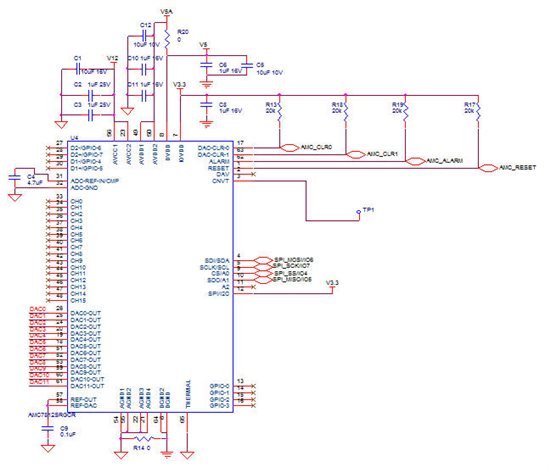
  • Above is the shematic of the DAC part of our board, there are 2 4.7uF tantalum capacitors in parallel on net V3.3 which is not showed here.

    About the bus captures, I can't provide a full and clear wave picture due to the capability of the oscope in my hand, but the wave looks good, and the dev id can't be read correctly if it's not good, right?

  • Zhu,

    There is a possibility that the timing on your microcontroller is more flexible than that of the AMC7812 and the read sequence does not exhibit issues that the write sequence will show, though unlikely. Ultimately I'm just exhausting every potential lead to fix your problem.

    I'll look at your schematic and get back to you soon.

  • Hi, Kevin.

    The problem had been fixed, it's your insist on timing check make me did a write wave check, and at last found a careless bug in my code.

    Thank you so much.

    Zhu

  • Zhu,

    Excellent news! Glad your problem is solved.

    Let us know if there is anything further we can assist you with.

  • Thank you, Kevin.

    I appreciate your help and look forward to meet you again.


    Zhu