This thread has been locked.

If you have a related question, please click the "Ask a related question" button in the top right corner. The newly created question will be automatically linked to this question.

ads1278 evaluation board problem

Hi,

I am in the middle of designing a Data acquisition system ADS 1278 seems perfectly fit. So I bought the evaluation  board and try to feed a differential input via an external THS 4520 FDA (which converted my single supply to differential). But the channels having the buffer/anti aliasing filter filter is not working properly, as I am not getting any output even though I have changed the switches to the buffer. I tried with directly feeding single ended supply through these channels, yet not getting anything. But from Channel 5 to 8 I am getting perfect output. What could be the problem? I did not find any jumper issue, may be I am unaware also, please help me.

Second issue is, I tried to get a gain of 10  by changing the FDA circuit by changing the resistors (of channel 2), but I did not get anything at out put of THS 4521 on EVL board. I have not take onut the 1.5nF capacitor. I believe its a Low pass filter with a cut off around 1KHZ. I used a low frequency signal below 500 hz but i could not get anything at the output across the resistor R23 or output pin of the amplifier. I used a single ended supply with source resistance 50ohm(function generator). Would that be a problem? I was getting not anything even a unbalanced one. 

Third, I am trying to convert a strain gauge signal which is a bridge of 350 ohm which has an output as low as  less than 1mv. I need a gain approximately near 1000 before feeding to ADS 1278. I dont have a instrumentation amplifier. If the first and second problem is solved, is it a crazy idea to use two or three FDA's in the EVL board with gain 10 each and get an output equivalent to 1000 by cascading one other and feeding to another channel to get an output .? 

  • Niranjan -

    For reference, which version of the EVM do you have?

    If you have Rev E, you might check JP3; this is the jumper that powers down the buffer amplifiers.  Since channels 1-4 are buffers and Channels 5-8 are not, this would explain your issue.

    Regarding the gain change, you may need to examine the circuit mods you made to make sure the circuit is still stable.  Just changing the gain settings may be causing you problems.

    Regarding large gain, you certainly can achieve large gain in multiple stages; typically this is the best approach.  Care should be taken with large gain values like this to make sure and limit the noise sources since any noise will be gained up and potentially impact the accuracy of your measurements.

  • Thank you Greg. I solved the channel 1 to 4 problem. It is because I hooked up a single ended supply from function generator, i hope. Currently I given through a differential output from a FDA(THS 4520),  from outside and the channel 4 to 8 is working. But I am not getting any gain even though I have changed the gain resistors. I tried two circuits for getting gains:- 100 ohm to 1k and 1k to 10 k(for THS 4521 on the board). But still not getting any gain and on the contrary I am getting some attenuation. Even for the buffer amplifiers/active filter which was there in the circuit from the beginning, I am getting a small attenuation. How could I find the stability? Its a normal intuition that 100 to 1K will work for gain 10 for a differential input coming from another differential amplifier. But I am not even getting a gain of 1. If I could solve for one stage, I could easily get the whole circuit working. 

    If we look at the schematics each buffer circuit there is a 50 ohm between capacitor and the gain resistor on feedback loop. I still did not understand the significance of the 50 ohm there. If you could throw some light, it would be great. And thanks again for the help greg.

    And yes its REV E.

    thanks again greg for the help

  • HI,

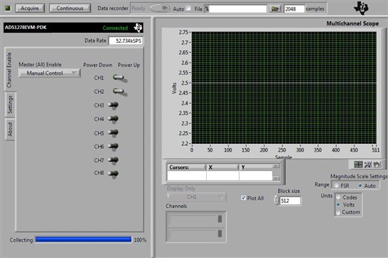
    More updates. I am currently able to get a gain through the differential amplifier on the board. I changed the buffer amplifier on channel 2 and 3 to get a gain of 10 each. I am using an other external ths 4520 of gain 10 to get a total gain of 100. It is avalable across the channel input. But, my current problem is, ADC pro is not detecting any signal in any channel. It responds once in a while and gives a perfect output, but most of the time a perfectly 0 output not even an noise? What could be the trouble.?? Hot to trouble shoot???

  • Hi,

    I was using ADS 1278 for a while. Everything was working fine and now what ever be the input to any of the channel I was getting this

    For more information, I am getting my input voltage with out any loss through the amplifiers till the input of the ADC chip. I have changed the gain of channel 2 and channel 3 buffer amplifiers to gain 10 and it also working fine when I checked at the our put of the amplifier. If you have any idea to trouble shoot please let me know.

    Regards

    niranjan

  • Niranjan -

    What OS are you using? Have you changed any of the jumpers/switches/configuration from the default settings (as shown in user guide)?  Did you power off or unplug the power to the motherboard without closing the software?

  • I am using windows 7.  In my knowledge I am keeping all the switches on position except I took away JP3 away to make my transistors working. I am slightly confused on some description on the manual. They have written J3 is the input buffers power down. But its JP3 which is input buffers power down when short and when open its powered up. J3 is the jumper through which we feed the input right? And its JP2 and JP1 is responsible for FSR and FSX not J1 and J2 right?

    As per the manual I have keprt S1 and s2 off. S6 selected on FS, JP2 on FSR, S3 on internal clock and the channels i used to keep changing from buffer to non buffer. Is there any way I could analyse the output from the DOUT lines pin J2, because, I am pretty sure there is ample amount of input (minimum I given is 73 mv) on the channel input of the chip when I checked with my volt meter. If I could check the output in the same manner, I could make sure its something in the interface.

    If you need any more information please let me know.

    Regards

    niranjan