


Dear Community,
I already managed to measure voltages correctly and setup the SPI communication between the ADS 1216 and ATMega16. However, if I send the read command (&B00000001), I receive four instead of three bytes from the ADC. The first one is always 248 if the mux register (01111000) is written and read within one reading cycle with the data read statement (see code). If the mux register is set with 01111000 only once before the reading loop, I get no response for the read command for the entries in the mux register and hence no reasonable ADC data. CS is tied low all the time, Dsync is always high.
I would really appreciate if somehone has any hints why I get more bytes than expected and why the second code doesn't work, although it's pretty similiar to the first one. Many thanks in advance!!!
Constantin
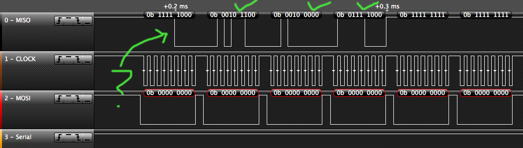
Here's the result of the mux register read command (1st byte strange, 2nd correct): mux register written and read before every data read command
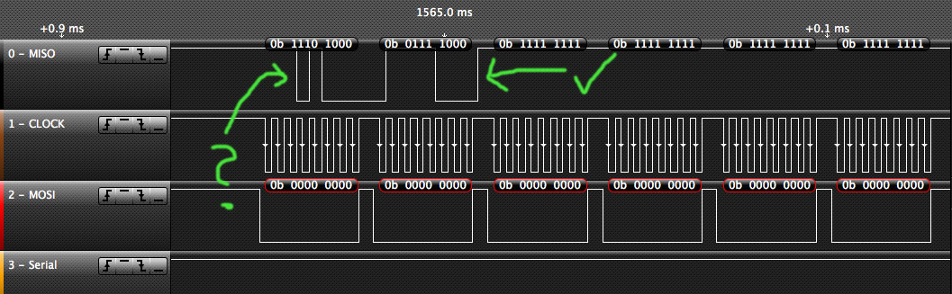
And the answer after the read command (again, 1st byte nonsense, rest is fine): mux register written and read before every data read command
The corresponding Code:
----------------------------
$regfile = "m16def.dat"
$crystal = 4915200
$baud = 19200
'd_in (35) -> MOSI (1)
'd_out (36) -> MISO (2)
'sclk (34) -> sck (3)
'dsync (29) -> a3 (34)
'pdwn (27) ->a2 (35)
'reset (24) -> pb0 (40)
'drdy (32) -> pb2 (42)
'pol (28) -> pb3 (43)
'cs (33) -> ss (44)
Config Portc = Output
Config Porta = Output
Config Pina.3 = Output
Config Pina.2 = Output
Config Pinb.0 = Output
Config Pinb.1 = Output
Config Pinb.2 = Input
Config Pinb.3 = Output
Config Pinb.4 = Output
Dsync Alias Porta.3
Pdwn Alias Porta.2
Reset_pin Alias Portb.0
Buf_en Alias Portb.1
Drdy Alias Portb.2
Pol Alias Portb.3
Cs Alias Portb.4
Waitms 1
Set Reset_pin 'reset
Waitms 1
Reset Reset_pin
Waitms 1
Set Reset_pin
Reset Buf_en 'no buffer
Set Pdwn 'no power down
Reset Pol
Reset Cs 'select chip
Set Dsync
Dim A(10) As Byte
Dim B(10) As Byte
Dim C As Byte 'no of input bytes
Dim Result As Long
Dim Temp As Long
Dim Gain As Single
Dim Ref As Single
Dim Voltage As Single
Ref = 2 * 2.5
Gain = 1.0
Result = 0
Temp = 0
C = 6
Waitms 10
Config Spi = Hard , Interrupt = Off , Data Order = Msb , Master = Yes , Polarity = High , Phase = 0 , Clockrate = 16 , Noss = 1
Spiinit 'init the spi pins
Waitms 10
'Selfcal begin
A(1) = &B11110000
Spiout A(1) , 1 'selfcal
'Selfcal end
'Initial register config: MUX begin
A(1) = &B01010001 'access: mux red´gister adress 01
A(2) = &B00000000 '1 byte to send
A(3) = &B01111000 'test pattern: here: a7 (pos) incom (neg) = 120 (dec)
Spiout A(1) , 3 'write 2 bytes a(1), a(2)
Waitms 1
'Test register config: read MUX
A(1) = &B00010001
A(2) = &B00000000 'access mux register
Spiout A(1) , 2 '1 byte to read,check mux
Waitms 1
Spiin B(1) , C
'Initial register config: MUX end
Waitms 1
'Setup test begin
A(1) = &B01010000 'access: acr register adress 01
A(2) = &B00000000 '1 byte to send 'test pattern: incom (pos) incom (neg
A(3) = &B00001100 'no buffer
Spiout A(1) , 3 'write 2 bytes a(1), a(2)
Waitms 1
'Setup test end
Do
Portc = &B11111111 'LEDs blinking
Waitms 200
Portc = &B00000000
Waitms 10
'Initial register config: MUX begin
A(1) = &B01010001 'access: mux register adress 01
A(2) = &B00000000 '1 byte to send
A(3) = &B01111000 'test pattern: incom (pos) incom (neg)
Spiout A(1) , 3 'write 2 bytes a(1), a(2)
Waitms 1
'Test register config: read MUX
A(1) = &B00010001
A(2) = &B00000000 'access mux register
Spiout A(1) , 2 '1 byte to read,check mux
Waitms 1
Spiin B(1) , C
'Initial register config: MUX end
Waitms 1
A(1) = &B00000001
Spiout A(1) , 1 'read data
Waitms 1
Spiin B(1) , C
Waitms 1
Print "coeff:begin"
Print B(1)
Print B(2)
Print B(3)
Print B(4)
Print B(5)
Print B(6)
Print "coeff:end"
Result = B(2) * 65536
Temp = B(3) * 256
Result = Result + Temp
Result = Result + B(4)
Print "result"
Print Result
Ref = Ref / Gain
Voltage = Result / 16777216
Voltage = Ref * Voltage
Voltage = 1000.0 * Voltage
Print "Vol"
Print Voltage
'two´s complement begin
If B(2) > 127 Then
B(4) = B(4) - 1
B(4) = Not B(4) 'invert
B(3) = Not B(3) 'invert
B(2) = Not B(2) 'invert
Result = B(2) * 65536
Temp = B(3) * 256
Result = Result + Temp
Result = Result + B(4)
Print Result
Voltage = Result / 16777216
Voltage = Ref * Voltage
Voltage = 1000.0 * Voltage
Voltage = -1.0 * Voltage
Print "Vol2"
Print Voltage
End If
'two´s complement end
Waitms 500
Loop
End
----------------------------
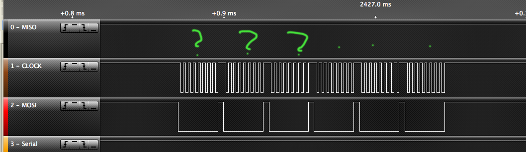
If the mux register is set only once before reading the data, even the mux register fails to be read. Write to Mux: Mux-Register, 1 Byte, 01111000
No response??
The corresponding Code:
----------------------------
$regfile = "m16def.dat"
$crystal = 4915200
$baud = 19200
'd_in (35) -> MOSI (1)
'd_out (36) -> MISO (2)
'sclk (34) -> sck (3)
'dsync (29) -> a3 (34)
'pdwn (27) ->a2 (35)
'reset (24) -> pb0 (40)
'drdy (32) -> pb2 (42)
'pol (28) -> pb3 (43)
'cs (33) -> ss (44)
Config Portc = Output
Config Porta = Output
Config Pina.3 = Output
Config Pina.2 = Output
Config Pinb.0 = Output
Config Pinb.1 = Output
Config Pinb.2 = Input
Config Pinb.3 = Output
Config Pinb.4 = Output
Dsync Alias Porta.3
Pdwn Alias Porta.2
Reset_pin Alias Portb.0
Buf_en Alias Portb.1
Drdy Alias Portb.2
Pol Alias Portb.3
Cs Alias Portb.4
Waitms 1
Set Reset_pin 'reset
Waitms 1
Reset Reset_pin
Waitms 1
Set Reset_pin
Reset Buf_en 'no buffer
Set Pdwn 'no power down
Reset Pol
Reset Cs 'select chip
Set Dsync
Dim A(10) As Byte
Dim B(10) As Byte
Dim C As Byte 'no of input bytes
Dim Result As Long
Dim Temp As Long
Dim Gain As Single
Dim Ref As Single
Dim Voltage As Single
Ref = 2 * 2.5
Gain = 1.0
Result = 0
Temp = 0
C = 6
Waitms 10
Config Spi = Hard , Interrupt = Off , Data Order = Msb , Master = Yes , Polarity = High , Phase = 0 , Clockrate = 16 , Noss = 1
Waitms 10
Spiinit 'init the spi pins
Waitms 100
'Selfcal begin
A(1) = &B11110000
Spiout A(1) , 1 'selfcal
'Selfcal end
Waitms 5
'Initial register config: MUX begin
A(1) = &B01010001 'access: mux register adress 01
A(2) = &B00000000 '1 byte to send
A(3) = &B01111000 'test pattern: incom (pos) incom (neg)
'A(3) = &B01110110
Spiout A(1) , 3 'write 2 bytes a(1), a(2)
Waitms 1
'Test register config: read MUX
A(1) = &B00010001
A(2) = &B00000000 'access mux register
Spiout A(1) , 2 '1 byte to read,check mux
Waitms 1
Spiin B(1) , C
'Initial register config: MUX end
Waitms 1
Do
Portc = &B11111111 'LEDs blinking
Waitms 200
Portc = &B00000000
Waitms 10
A(1) = &B00000001
Spiout A(1) , 1 'read data
Waitms 1
Spiin B(1) , C
Waitms 1
Print "coeff:begin"
Print B(1)
Print B(2)
Print B(3)
Print B(4)
Print B(5)
Print B(6)
Print "coeff:end"
Result = B(2) * 65536
Temp = B(3) * 256
Result = Result + Temp
Result = Result + B(4)
Print "result"
Print Result
Ref = Ref / Gain
Voltage = Result / 16777216
Voltage = Ref * Voltage
Voltage = 1000.0 * Voltage
Print "Vol"
Print Voltage
'two´s complement begin
If B(2) > 127 Then
B(4) = B(4) - 1
B(4) = Not B(4) 'invert
B(3) = Not B(3) 'invert
B(2) = Not B(2) 'invert
Result = B(2) * 65536
Temp = B(3) * 256
Result = Result + Temp
Result = Result + B(4)
Print Result
Voltage = Result / 16777216
Voltage = Ref * Voltage
Voltage = 1000.0 * Voltage
Voltage = -1.0 * Voltage
Print "Vol2"
Print Voltage
End If
'two´s complement end
Waitms 500
Loop
End
----------------------------

