This thread has been locked.

If you have a related question, please click the "Ask a related question" button in the top right corner. The newly created question will be automatically linked to this question.

MSC1210 Vref clock


Hello,

I am trying to compare the MSC1211 and MSC1210. In the MSC1211 data sheet, the internal voltage reference is specified for a Vref clock of 250 kHz. Am I correct in understanding that this is a maximum frequency?

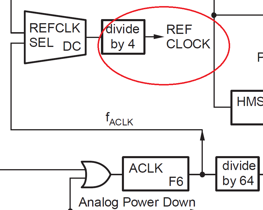
The MSC1210 data sheet in a similar table states "ACLK = 1 MHz." Does that mean the ACLK divider must be set so that the Vref clock is 1 MHz? Is that a minimum or a maximum? What are the consequences of using a different frequency?

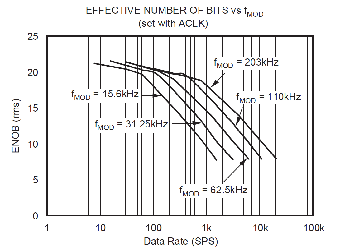
I am asking this because the ADC rate depends on the same branch of the clock division tree, and it would be helpful to know how constrained the ADC rate really is, especially with the MSC1210.

Thank you,

Chris Hakim

  • Hi Chris,

    The two devices, though similar, are still different and the register settings are different.  The MSC1210 derives the reference related to the ACLK, as does the modulator rate, conversion rate, etc..  To see the responses that are typically shown as well as for performance you should target your ACLK for 1MHz.  You can run a faster ACLK and your performance will affected as shown in the datasheet and as I have illustrated below.  ACLK is 64 times the fmod frequency.

    Best regards,

    Bob B

  • Hi Bob,

    Thank you for your reply. I am aware of the many performance graphs for the ENOB versus modulation frequency, decimation, etc. My question has to do with how much leeway I have with regards to the clock that goes into the internal reference cicuit. Must I always stick with 1 MHz for the MSC1210 and 250 kHz for MSC1211? If not exactly those figures, is it better to exceed or go below? What are the consequences of deviating from the ideal frequency?

    Chris


  • Hi Chris,

    When you change the modulator rate you also change the filter characteristics relative to the decimation.  In other words at high mod rates you lose any capability of 50-60Hz rejection.  It really depends on your bandwidth of interest and noise relative to your needs.  Another problem with high mod rates is using the unbuffered mode which radically affects the input impedance and greatly lowers the impedance as the mod rate increases.

    Best regards,

    Bob B

  • Bob,

    My question does not concern the modulator clock, but the fact that a derived clock goes into the internal voltage reference, i.e.:

  • Chris,

    In the original post you asked how it relates to the MSC1210 (as does the title of the posting)...now you show the picture of the MSC1211 block.  In my first post I told you the register settings and control of the two devices are different.  For the MSC1210 specifically, the ACLK drives the reference and the modulator clock.  You can't change one without the other.  If you change ACLK you change both reference and modulator clocks.  So yes, you affect the mod clock.

    The MSC1211 has an extra option to drive the reference. This allows the ability of keeping the reference clock around 250kHz and driving the modulator clock at a higher frequency.  This option does not exist for the MSC1210.

    What this boils down to is the device is designed for ACLK of 1MHz.  The problem is with dividing some crystal values down to get an exact value of 1MHz.  The idea is to get something close.  The reference would like to see 250kHz (MSC1211 REFCLK which is a divide by 4 or UCLK or ACLK) or 1MHz (MSC1210 ACLK).  The reference output is only tested in production tests for this condition.

    Another option would be to provide an external reference. In this case you don't have to worry about the reference clock timing at all.

    Best regards,

    Bob B