This thread has been locked.

If you have a related question, please click the "Ask a related question" button in the top right corner. The newly created question will be automatically linked to this question.

WaveVision 5 acquiring I and Q channel data sequentially from ADC12D1800RFRB

Other Parts Discussed in Thread: ADC10D1000

Hello,

I am interfacing with the ADC12D1800RFRB using the WaveVision 5 software. The system is transmitting symbols in short packets followed by some downtime. As expected, an oscilloscope trace shows that I and Q data line up in time (e.g. start of packet occurs on I and Q channels at the same time).

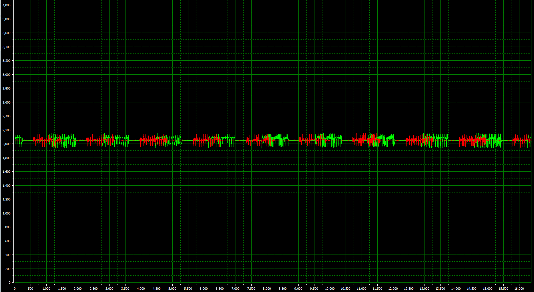
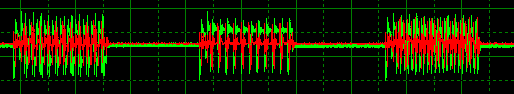
Unfortunately, I and Q data does not align as expected when viewed in the WaveVision 5 software. When operating in non-DES I and Q mode and 16K samples, it appears that WaveVision 5 is showing the I data from the first 16K symbols and then the Q data from the next 16K symbols. I need access to simultaneously sampled I and Q data in the WaveVision 5 software, not 16K samples with only I data then 16K samples with only Q data. I have reviewed the WaveVision 5 and ADC12D1800RFRB user guides and haven't been able to find a solution to this problem.

Help?

Thanks,
Jared 

  • Hi Jared

    There is an updated FPGA configuration file that should take care of this issue. Here is the updated file:

     8004.adc10d1000_xc4vlx25_adc12d1600rfrb.zip

    hardware\fpga_images\

     Rename the existing file, adding a .old suffix. Then copy the new file into the same folder.

    Now when you re-start Wavevision and use the board it will use this new FPGA configuration. This should resolve the issues with I and Q data not being aligned when using the simultaneous I and Q capture mode.

    I hope this is helpful.

    Best regards,

    Jim B


  • Hello Jim,

    Thanks for your response. However, I think you gave me an image for the wrong ADC. I am using the ADC12D1800RFRB, and the provided image is for the ADC12D1600RFRB.

    Could you please provide me with a similar solution for the ADC12D1800RFRB? I would really appreciate it.

    Thanks,

    Jared

  • Hi Jared

    The ADC12D1800RFRB and ADC12D1600RFRB use the same common FPGA configuration file. If you look in the destination folder I indicated you will find that there is no file named "adc10d1000_xc4vlx25_adc12d1800rfrb.bit" only one named "adc10d1000_xc4vlx25_adc12d1600rfrb.bit".

    Please give it a try and let me know if it resolves the issue.

    Best regards,

    Jim B

  • Hello Jim,

    I just made the suggested changes: replacing the adc10d1000_xc4vlx25_adc12d1800rfrb.bit file with the adc10d1000_xc4vlx25_adc12d1600rfrb.bit file in the zip folder provided (after renaming it to *1800rfr.bit.

    The issue remains. Here is a screenshot to show you what I am seeing:

    The two channels (I in red, Q in green) both have data or no data (flat) at the same time when transmitted. When probing the I and Q signals just before entering the ADC, the green and red pulses you see in the image above are lined up. However, this is not the case in the WaveVision 5 GUI; from viewing in WaveVision 5, it seems that "n" I samples are read, then "n" Q samples. I have confirmed this by labeling the individual packets and observing that the last packet observable on the right side of the window on Channel I is the same as the first packet observable on the left side of the window on Channel Q. All packets are the same length. You'll notice that if you observe the partial last red packet and the partial first green packet on the image above... they add up to be a full packet.

    The new FPGA image did not seem to fix this problem (this is exactly the problem I was observing before). Is there a step I missed? Does this differ from the behavior you are seeing? Is there something I might be doing incorrectly in WaveVision 5 (I am using I and Q non-dual-edge-sampling, 16K samples per channel, single-capture mode instead of continuous)? I really need to have this fixed soon.

    Thanks for your patience.

    Jared

  • Hi Jared

    Please check the behavior with reduced sample lengths. Try 8k per I/Q and 16k per I/Q. Let me know if that helps.

    Best regards,

    Jim B

  • Hello Jim,

    The problem persists with 4K or 8K samples per I/Q channel. The screenshot exhibits identical behavior (I and Q not lined up in WaveVision 5, but lined up on transmission and right before entering ADC on oscilloscope).

    Jared

  • Hi Jared

    I just re-read your text above: "I just made the suggested changes: replacing the adc10d1000_xc4vlx25_adc12d1800rfrb.bit file with the adc10d1000_xc4vlx25_adc12d1600rfrb.bit file in the zip folder provided (after renaming it to *1800rfr.bit."

    That is not what I said to do. I said to re-name the existing "adc10d1000_xc4vlx25_adc12d1600rfrb.bit" file to add the suffix .old. Then copy the new file into the folder without changing the filename at all.

    There is a file (image_map.xml) in the Wavevision structure that directs it to use the file "adc10d1000_xc4vlx25_adc12d1600rfrb.bit" directly for the ADC12D1800RFRB. There is no file "adc10d1000_xc4vlx25_adc12d1800rfrb.bit " in that directory.

    Here is the directive in image_map.xml.

    "        <!-- ADC12D1x00RF: The 1800RF RB board version loads the same FPGA image as the 1600RF version. Ryan Bruno 2011-06-27 -->
            <exception nick="adc10d1000" dut_full_name_condition="adc12d1800rfrb"    override="adc10d1000_xc4vlx25_adc12d1600rfrb"/>"

    Please try doing exactly what I said and let me know if the I and Q data are properly aligned. If you are using a Windows 7 computer you may also have to ensure that it is really using the new file. I have run into issues with Windows 7 file protection preventing these updates in the C:\Program Files\ area.

    I hope this is helpful.

    Best regards,

    Jim B


  • Hello Jim,

    Thank you for the second observant look at my post. Lesson learned: always describe exactly what you did (and do exactly as told) when trying to remotely debug hardware.

    Your solution works:

    This solution also cleared up a problem I was having with accessing 32K samples per channel.

    I very much appreciate your help. Now I can move forward on my project!

    Best,
    Jared 

  • Hi Jim,

    We're currently running into the same I and Q channel misalignment issue on the new ADC12D2000RFRB eval board (the ADC is fantastic, BTW).  Do you have an updated .bit file to replace the adc10d1000_xc4vlx25_adc12d2000rfrb.bit file that allows aligned capture of I and Q in non-DES mode?  [I did try the adc10d1000_xc4vlx25_adc12d1600rfrb.bit file you had kindly posted earlier, but of course that did not set up this board properly, so no surprise.]

    I also re-compiled the Virtex-4 firmware from the source provided, and the .bit file functions correctly, except for the channels not being aligned.  Can you point to what changes I should make in the Verilog source to fix the alignment issue myself, as I'm happy to re-compile the FPGA source.  Frankly, I'm surprised that a firmware change in the FPGA can overcome what appears to be a software limitation here, so I may be missing something subtle about this issue.

    Regards,

    Bernard Gunther

    Jim Brinkhurst84999 said:

    Hi Jared

    There is an updated FPGA configuration file that should take care of this issue. Here is the updated file:

     8004.adc10d1000_xc4vlx25_adc12d1600rfrb.zip

    hardware\fpga_images\

     Rename the existing file, adding a .old suffix. Then copy the new file into the same folder.

    Now when you re-start Wavevision and use the board it will use this new FPGA configuration. This should resolve the issues with I and Q data not being aligned when using the simultaneous I and Q capture mode.

    I hope this is helpful.

    Best regards,

    Jim B


  • Hi Bernard

    Please try this file for that board. 1018.adc10d1000_xc4vlx25_adc12d2000rfrb.zip

    It should resolve the issue. If it does not, please let me know.

    This newer file will be included in a new Wavevision 5 installer coming soon.

    Best regards,

    Jim B

  • Hi Jim,

    Thank you for the post--you beat me to a solution by just a few hours!  I can confirm that the new .bit file does work fine, and now allows properly aligned capture in non-DES I+Q mode up to 32k samples.

    As possible help to others, I have also posted my own fix 7181.adc12d2000_rfrb.zip to the Verilog firmware should people wish to recompile the Virtex-4 from sources (like we're doing in PlanAhead 13.4).

    If you look at my amended code, you'll see that the basis for the fix is to separate the FIFO read enable registers into individual I and Q controls.  This allows the I samples FIFO to be read independently without inadvertently asserting read enable on the Q FIFO.  Otherwise (the existing code) would read both FIFOs at once, and effectively skew one channel by the capture size.

    Regards and thanks,

    Bernard Gunther

    Jim Brinkhurst84999 said:

    Hi Bernard

    Please try this file for that board. 1018.adc10d1000_xc4vlx25_adc12d2000rfrb.zip

    It should resolve the issue. If it does not, please let me know.

    This newer file will be included in a new Wavevision 5 installer coming soon.

    Best regards,

    Jim B