This thread has been locked.

If you have a related question, please click the "Ask a related question" button in the top right corner. The newly created question will be automatically linked to this question.

How to connect three 2-wire RTD in the same LMP90100 ?

Other Parts Discussed in Thread: ADS1248, LMP90100

Hello

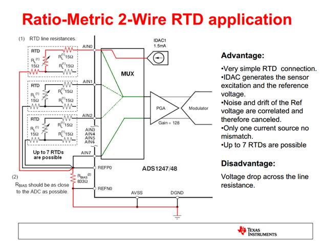
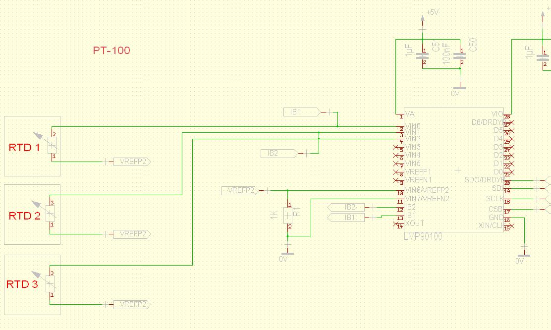
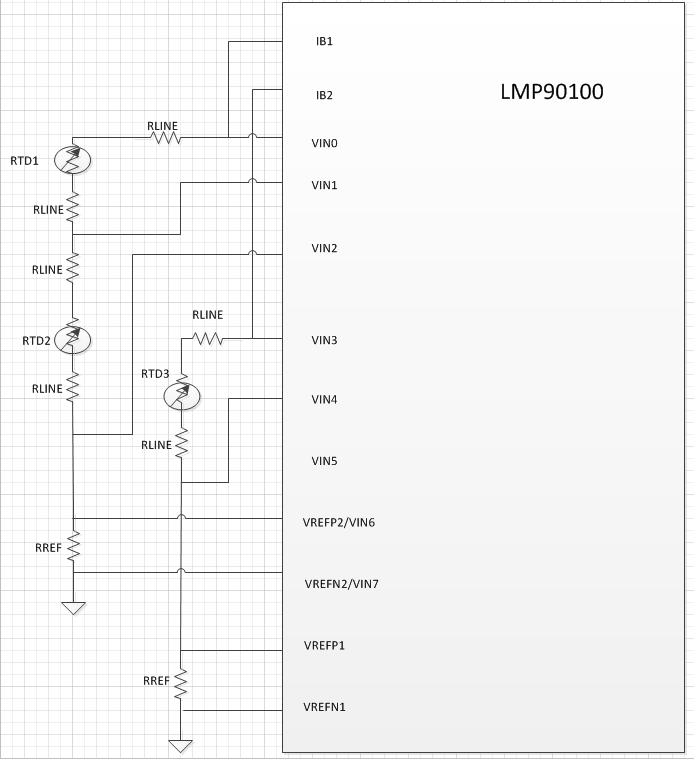
I'm developping a system where I'm meassuring a 3 RTD in a 2 wire method, and i want to use the all 3 RTD in the same LMP90100, but I don't know how to connect the PIN VREFP1/2 and VREFN1/2 for all 3 RTD 2 wire method, this is the circuit tha t I did and I'm not sure if it must be connect like that.

  • Hello Badreddine, I looked at your schematic and unfortunately that scheme will not work. When you connect the RTDs in parallel like shown the one current source (IB1) will be divide across each RTD leg. However the current into each leg will depend on the RTD resistance which will in turn change based on the measured temperature. In affect your IB will fluctuate with temperature and you will no longer have a constant know current source which is needed to extract the RTD resistance.

    As a colleague suggested you could try connecting two RTDs in series and use one current source and use the second current source on the third RTD. Just make sure that you're within the complaince range of the current sources, pins IB1, IB2 are at least 0.8V below VA.

    Also take a look at the ADS1248.

  • Hello Jason, thank you for Your reply,  I have done some modification on my schematic :

    - I connected the firts currnet IB1 with one RTD, and the second Current IB2 with the second ans the third RTD.

    - For the resistance REF between VREFP2 and VREFN2 I have chosen Rref = 1Kohms.

    - And I want to ask you another question about the same composant LMP90100 but with three Thermocouples.

     I attached a schematic for the RTD anf for THERMOCOUPLES, if you can tell me if there is somthing wrong.

    Thank you for your reply

    Best regards

    Badreddine EL HANOUCH

  • Badreddine,

    Still the way it is setup is that IB2 will go into the parallel legs of RTD2 and RTD3. RTD2 and RTD3 will need to be in series.

    Schematic of 3 thermocouples looks good. Can I ask the intent of the 2k||2k resitors on each leg of the thermocople?

  • Jason,

    - For the RTD I don't know how to connect two RTD in series because every RTD (RTD2, RTD3) is connected to Input ( VIN1 and VIN2) ?

    - For the 2K//2K resistors I have seen the schematic on the evalutaion board of the LMP90100 and I didnt understund what is the aim of this, because on the datasheet i didn't find it ?

    Best regards

    Badreddine EL HANOUCH

  • See attached for what I had in mind for RTD's in series.

    The 2K/2K parrallel network on the the board was placed for balancing experimentation. One resistor can be shorted and the other opened to match the datasheet.


  • Thank you for your apply, 

    - For the Rlines Resistors, I have seen on the evalution board that there are not connected, contrary on the datasheet and what you sent me ? If it is nessecary to have a Rline resistors what's about the value and the role of these resistors ?

    -  I didn't find a good explanation on the datasheet about the pins D0,D1,D2...D6, if it's necessary to connect them ?

    - About the margin of temperature if it can be between 0° To 250° Celcus for the RTD and THERMOCOUPLES connection ?

    Thank you

    Best regards

    Badreddine EL HANOUCH

  • Hello Badreddine,

    - The Rline resistors are not separate individual resistors. They are the modelled line resistance inherent to each RTD. If you think of an RTD model represented in schematic form you have the RTD itself which is a temperature dependent resistor with additional  Rline resistance for each wire of the RTD.

    - D0-D6 are GPIO which can be used to drive LEDs and switches or read. It is not necessary to connect them.

    - Margin of temperature depends on the temperature rating of the RTD and Thermocouple you have. You can see their datasheets for specifications.