This thread has been locked.

If you have a related question, please click the "Ask a related question" button in the top right corner. The newly created question will be automatically linked to this question.

ADS FFT parameter mismatch problem

Friends,

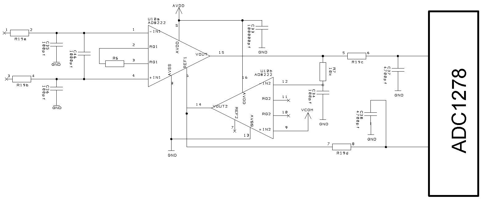
I have tested out the FFT analysis using 1278 EVM using ADC pro software with the same specification as data sheet with 1v(tied different amplitude up to full scale) sine wave of frequency 1Khz generated using Agilent 33250A function generator. Input is fed through the channel 4 with buffer on (buffer off also) which I believe will be changing to a differential signal and feeding to the ADC in high speed mode(tried different modes also). The best SNR value I got was way low than the datasheet specification for the same settings. The values I got are shown below

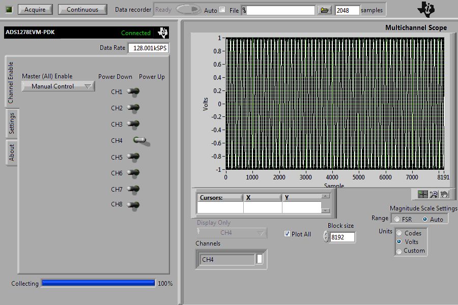
I have two evaluation board and tried with both, but getting same results. According to Data sheet minimum SNR is 101 and THD is THD -108 etc. I may be missing out something basic in this test setup. Could you please point out that?

  • Niranjan -

    A couple things to point out -

    1. Typically, you would not measure performance with full scale input.  Usually, the magnitude is -0.5dBFS; this removes any possibility of non-linearities that may  occur near the positive and negative power rails due to head room.
    2. Take a look at your signal source - generally they are not as clean as you might think they are. Your function generator is only 12bits, so the theoretical max is around 74dB!  It is not uncommon to have to low-pass filter a signal generator with a steep roll-off pass-band to ensure a very clean signal going into the ADC.  Keep in mind you can't measure better than your signal source.  A quick test for noise floor items is to short the ADC inputs and then observe the noise floor/histogram code spread/etc.
    3. For best performance, you need to make sure that you are coherently sampling. 
  • Thanks Greg that's a great tip. 

    I am on the way of designing a Data acquisition system. So from your reply, I understood the test setup I am currently using have a many limitations and So, even theoretically, I won't get good results. If you could provide the information about the test set up TI is using for these ADCs that would be really helpful. For example the signal generator you guys used for generating a good signal, any grounding guidelines etc. 

    In our system design, I currently have two low pass filters:- 1) pre Instrumentation amp and 2) Post In amp with a specified cut off frequency according to our design. I am able to find a frequency response of the filters which is satisfactory. Now, I need to test the whole noise characteristics of the whole system and then I bumped into this trouble. So, If you could provide some information about the test setup, that would be a great starting point for me and it will be a great help for my project. For more information, I am attaching a schematic of a single channel of the system I wanted to test.

    Thanks again for your help