This thread has been locked.

If you have a related question, please click the "Ask a related question" button in the top right corner. The newly created question will be automatically linked to this question.

VCA8613 CW mode

We tried to use device in CW mode

http://www.ti.com/lit/ds/sbos200f/sbos200f.pdf

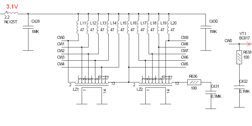
p.15: "The CW outputs are typically routed to a passive delay line, allowing coherent summing of the signals."

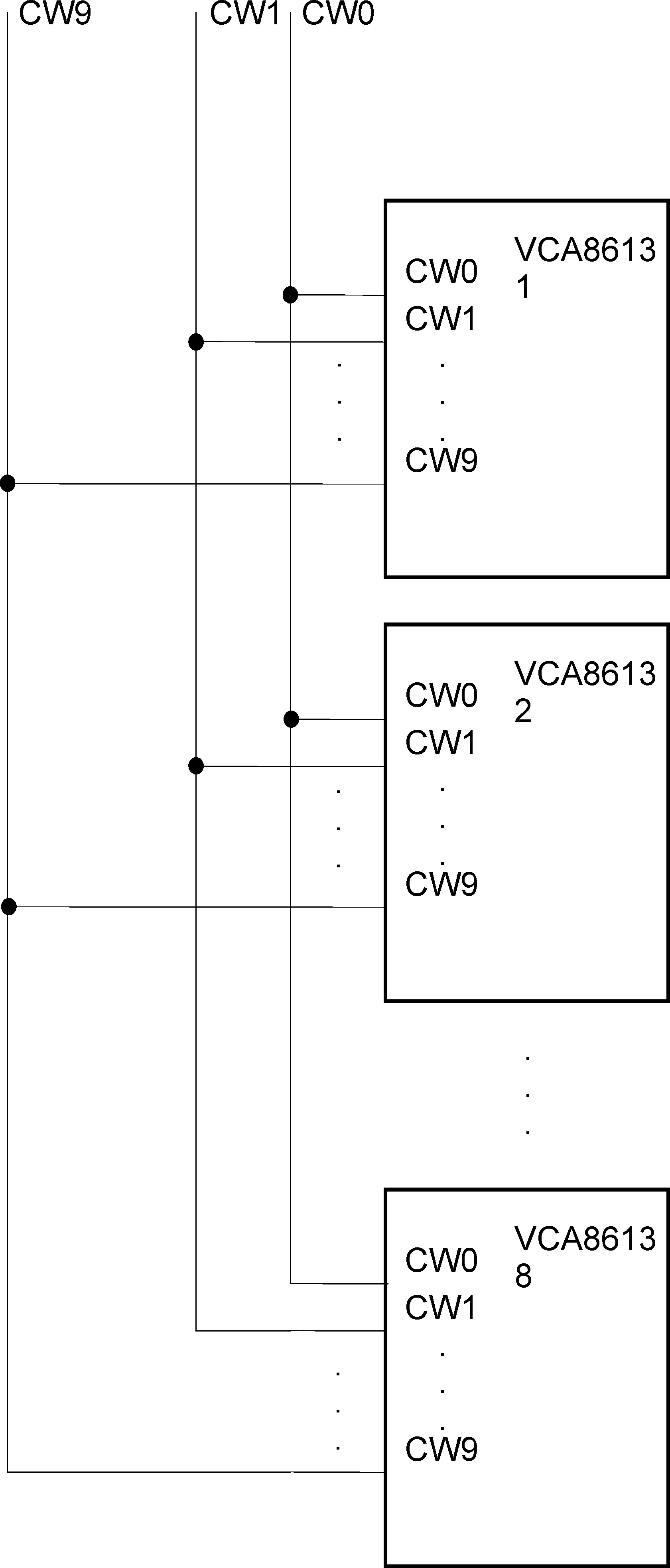
We connected outputs to delay line IC, provided 3,0 V on CW output pin and found that device CW output pin is bypassed.

But in pdf we can see info that device CW output is current output and not any info (inpedance, capacitance etc) about

these outputs parameters.

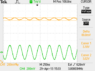
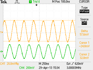
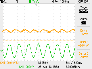
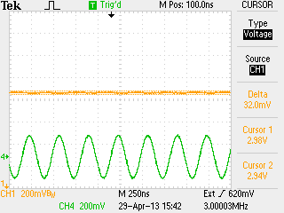
We have test. Connect from external generator signal to delay line and:

 - when CW outputs are disconnected we see this signal on delay output line.

 - when CW outputs are connected we practically can't see this signal on delay output line.

Delay line is passive (inductors and capasitors).

All voltages on device pins are according with pgf.

  • Yes, the CW output pins need 3-3.3V for the compliance voltage.

    Are you tieing the 3V directly to the output line?

    The compliance voltage needs to be tied through an inductor or from the inverting input of an op amp circuit. This is shown in figure 3 and 4.

    The output also requires a 2mA to 2.5mA current that the compliance voltage needs to generate.

    Do you have a schematic of your circuit that I can see?

  • All CW0-CW9 connected parallel to 8 VCA chips.

  • Let me get this straight. Each one of your CW outputs are connected to a separate VCA8613? Which would mean your have 9 total in this circuit?

    They are not connected through an inductor or inverting input of an op amp?

    If you have a schematic I can see that would really help.

  • Our complete drawing has 23 sheets.

    I send VCA connection block diagram.

    We don't use any active components (op amp, transistor)  between VCA (8 pcs) and delay line. 10 inductors for providing +3V only.

    CW pins in this block diagram are connected to CW pins in first drawing.

  • I'm not sure that my 2 drawings was loaded to TIE2E...

    Do you see my files CW_problem.png and last VCA_connection.png?

  • Can you probe the CW output line?

    I'm not sure how easy this would be, but I would like to see what the CW output is without the delay line installed just to see if there is an output coming from CW0-CW9.

  • I send oscills.

    We have 8 pcs VCA.

    I connect generator to input of 1 of VCA channel.

    All VCA connected (programmed) to internal V+

    One channel of 1 VCA connected (programmed) to CW0

    Icheck signal on CW0 output (yellow).

    Input signal (green).

    Output DC

    Output AC

    On all CW Delay Lines pins I see similar signal with corresponding delays

    Then I connect all 7 VCA to CW1-9 (on VCA inputs practically gnd)

    bu 1 VCA connected to CW0

    and signal on Delay Lines disapperes (shunted by VCA outputs, my opinion)

    AC

    DC

    May be we CAN't connect VCA outputs to DELAY LINE directly without additional correct Voltage/Current buffer?

  • OK. A few questions.

    In Configuration 1:

    1. Is delay line connected? Is this possible to remove?
    2. Is the rest of the CW0 bus floating externally? or connected to 8 CW0 outputs and floating internally
    3. Does the output look correct with given gain settings?
    4. What does “AC” and “DC” mean? Coupling?

    In Configuration 2:

    1. What is difference?  Simply routing VCA inputs to CW1-9?
    2. Is delay line connected? Does CW0 have a dedicated delay line?
    3. “Then I connect all 7 VCA to CW1-9 (on VCA inputs practically gnd)”. Does this mean the other 7 VCA8613 chips? CW0 is connected to one channel of one VCA8613?
  • I haven't heard a response in a while. I wanted to make sure everything was going okay with your design. Please let me know if any other assistance is needed.

  • Excuse me for silence. Our problem was that in PCB was soldered 8617 IC'es instead of 8613. Thank you for high level support.