This thread has been locked.

If you have a related question, please click the "Ask a related question" button in the top right corner. The newly created question will be automatically linked to this question.

Problem Time conversion ADS1232

Other Parts Discussed in Thread: ADS1232

I have a problem in ADS1232 conversion time.
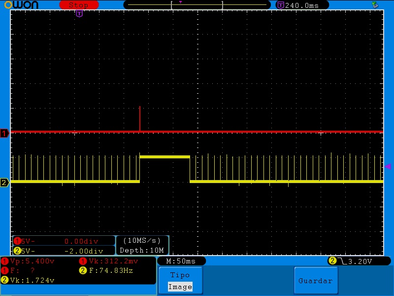
Hi I have a ADS1232 (with PGA128 and 80 SPS) and the SCLK pin to 0 V see which converts every 12 ns but when sending the 25 pulses after the last pulse 100ms to spend again to obtain other data.
If 10SPS change. get data every 800ms!
Any idea?

  • Hi Ariel,

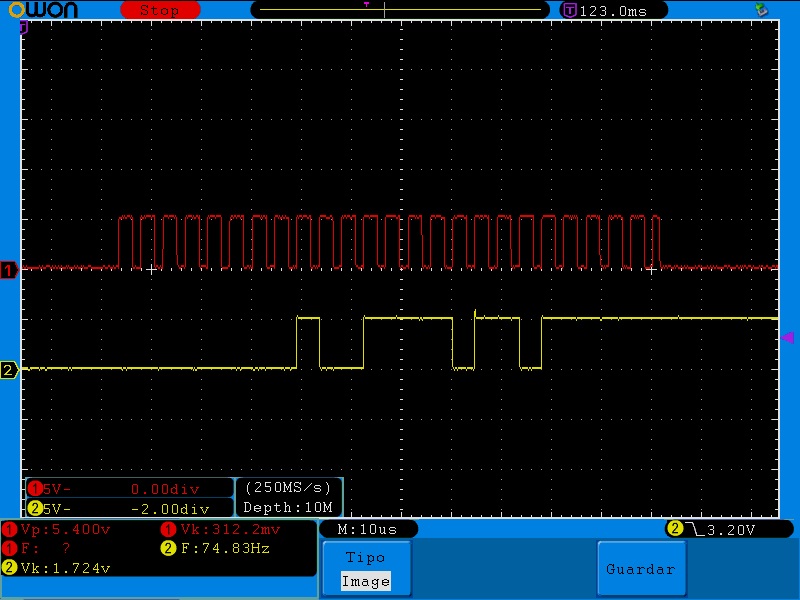
    Welcome to the forum! You might want to verify the number of clocks being sent with an oscilloscope or logic analyzer.  It sounds like you are actually sending 26 clocks instead of 25.  If you look at Figure 36 on page 20 of the datasheet you will see the same response as you are getting when running an offset calibration.  If you send 26 clocks you will start the offset calibration cycle that takes 100ms at 80sps, and 800ms at 10sps.

    Best regards,

    Bob B

  • Yes I verify-....

    20130626_625821.bmp figure shows 12 ns conversions and after 100ms.Figure 20130626_630001.bmp this with zoom and shows the 26 pulses.

    RED. clock   YELLOW: data

    y. 

  • Hi Ariel,

    You are definitely going into a calibration cycle.  The scope shot appears to be ok, but there may still be a very small glitch with the SCLK that may be creating 26th clock that doesn't show up in the picture. 

    Does the same result happen if you continually read?  What does the output look like if you send just 24 clocks?

    Best regards,

    Bob B

  • does exactly the same continuously reading and 24 clocks.

    I'm lost!

  • Ariel,

    How are you generating the SCLKs?  I noticed from the scope shot that the width of the last clock is different than the others.  At any time in your software do you change the port configuration?  Can you send me your schematic?  Are you using a prototyping system, or do you actually have a PCB where the micro/ADS1232 are installed?  Do you have bypass caps from power to ground at the supply pins of the device?  Sometimes grounding can also be an issue. 

    Best regards,

    Bob B

  • I corrected the last clock, same thing.

    Do not change the port settings. The schematic is basic only  a capacitor between CAP pins and pull down resistance on pin CLKIN/XTAL1. With the micro drive, A0 = 0V, temp = 0V, gain1 = 5v, gain0 = 5v, speed = 5v, pwr = 5v.I'm using a prototype, not a PCB.

    Best Regards

  • Ariel,

    I would try and improve the grounding around the part and place a 0.1uF cap as close to the pins as possble across DVDD and DGND.  The part is seeing glitching on the SCLK even though it doesn't show in the scope pictures.

    Another thing you could try is slowing down SCLK and placing 50 ohms of series resistance in the SCLK line to the ADS1232 to slow the edges so that the transitions do not ring.

    Best regards,

    Bob B

  • Thank you !!!!
    Fixed issue with a capacitor between clock and GND. !!

    Best Regards.