This thread has been locked.

If you have a related question, please click the "Ask a related question" button in the top right corner. The newly created question will be automatically linked to this question.

AFE0064 output current

Other Parts Discussed in Thread: AFE0064, ADS8363, DDC264

Dears,

I'm using two AFE0064 coupled with an ADS8363. I have broken one of the two chips and I do not know if there is something wrong in my setup. I was trying to get the linearity of the output versus the integration time, this is the setup:

- setting of the AFE: range 7, INPUTz=0, sequential mode Half clock cycle clock input 2MHz

- 10Mohm resistors connected to the AFE's inputs, one side of the resistor connected to a voltage variable from 0v to 1.7v.

At the beginning I set the voltage on the resistor to 0v and integration time 14us so I was expecting 1.68v/10Mohm*14us=2.35nC instead the response of the chip was about the 45% FS, then I set 50us IT and the output was about 65% and with 100us was 75% while I was expecting a full scale. I did the same test using 1.2v instead of 0v and the chip shows a good linearity from 0% to FS. I kept playing around with voltage and integration time and now the chip it is actually broken.

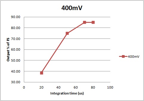
I couldn't find any indication on the data-sheet about a maximum input current or anything else which could justify this behaviour. I send you in attachment a graph of the output versus IT with 0.4v applied on the resistors when the chip was still working, any help will be really appreciated as we got 10 more board in production.


best regards

Iolanda

  • Hi Iolanda,

    On the failure: The AFE0064 will not get damaged as long as the input voltage at the pins are within the Abs max ratings mentioned in the datasheet. Also, try to limit the current onto any IN pin within 10mA, as sustained values of current more than that could damage the part.

    On the linearity of the device: The AFE0064 is meant to integrate charge packets, (example current pulses or charge from photo-diodes from a flat panel detector). The DDC series (eg DDC264) is more easily used for systems with continuous currents like the case you have mentioned. Nevertheless, you could use the AFE0064 part with the following information (these are not obvious in the datasheet because the part was not meant to take a continuous current):

    (1) The reset sample should be within 10% of the FS: The integrator enters feedback (ie exits reset) at 9th CLK rise (for simult mode) and hence immediately starts integrating any input current causing a non zero reset sample. Hence the input current should be small enough so that this charge integrated from 9th CLK rise to SHR rise edge must be < 10% of the range. For eg. with CLK = 1MHz, the input current is integrated for (64-8)*CLK+t3 = approx 56 CLKs = 56us before the reset sample is taken. Hence the input current for good linearity in range7 must be limited to < 9.6pC*0.1/56e-6 = 17nA. Linearity may be compromised if it exceeds 10% and in certain cases, the output may behave non-monotonically wrt input.

    (2) The device output corresponds to signal sample - reset sample: Since the part has a non-zero reset sample due to the constant input current between 9th CLK and SHR rise, the output will be lesser to that extent. 

    Please recheck the linearity with the above in mind.

    Regards,

    Nagesh

  • Hi Nagesh,

    thank you for your reply. Taking in account point 1 and 2 the linearity is ok. I am aware of the DDC264 and I am already using the evaluation board; only problem is that we do not have a facility to do assebly of the board and since the DDC264 cannot be hand solded we use the AFE until we can acces to a pick and place. Anyway, our application is suppost to measure charge packets, the linearity I was doing it is just a characterization of our data acquisition system.

    Regarding the failure, I am sure I didn't exceed neither the Abs max ratings nor 10mA per pin but the chip I was testing doesn't work anymore: EOC is always low, the voltage at the input pin is about 0.1V and the output is stuck. Maybe it was just a weak component...

    Thanks anyway,

    best regards

    Iolanda