This thread has been locked.

If you have a related question, please click the "Ask a related question" button in the top right corner. The newly created question will be automatically linked to this question.

ADS131 Temperature Sensor

Other Parts Discussed in Thread: ADS131E08EVM-PDK

I am getting strange results from trying to sense the ADS131 internal temperature using the inbuilt option.

Setting the CHnSET register to 0x14 returns a figure of approx 1.25V, if I calculate with PGA=1 and 4.096V (Internal) reference.

I get reasonable figures when measuring external input (0x10), or the AVdd/DVdd (0x13 for CH2 & 3) or Input Short (0x11) or External Test(0x15).

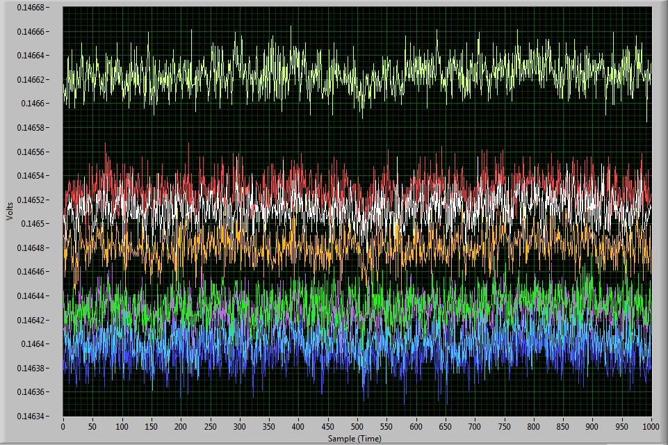
The given formula implies a figure of approx 0.168V for 25 degrees C, and the Temperature sensor is spec'd at 145mV at 25 degrees C (Electrical Characteristics Table)

Moreover, the reading seems to Increase with Decreasing temperature?

Was wondering if there is something obvious I'm missing in the data sheet - or an errata?

  • Are you doing the conversion externally? (converting codes to voltage to temp)

    Using the ADS131E08EVM-PDK and software with default settings and changing all input channels to Temp Sensor, the below data was captured to agree with the specs.  Perhaps there is a factor of 10 off in the calculation.  This would at least get you in the neighborhood of the data shown.

  • Greg,

    I'm getting approx 2,718,000 as a typical raw ADC count.

    At 4.096V reference = 4.096/2^23 = 0.488uV/bit => 1.32Volts - ish.

    Had figured maybe a x12 gain (by default inside the chip??) made sense, but the fact that it seems to go in reverse direction to that expected has me beat.

  • Something sounds off...are you reading the data yourself (external processor) or using the -PDK?

    Attached is the data corresponding to  the graph above (taken using the -PDK).  The last column shows conversion from hex codes to decimal and volts (for your reference).  If you are reading using your own processor, you may want to revisit the data capture to make sure that you are reading data correct.

    Also attached is the register settings for the device...these should be the -PDK defaults with 4V ref and Temp selected as input.

    7558.Device_0_RegMap.xlsx

    7180.Device_0_Codes.xlsx

  • Greg, Thanks for comprehensive reply.

    Yes using own PCB and processor, but everything else seems to be functional, Reading of own inputs, measuring AVdd and DVdd etc via input MUX works fine, shorting input via MUX also gives plausible answers, TEST input also selectable and gives good results, just the temp that seems to be odd. (Guess its faulty inside the ADC?). Will build up second board and test against that. Its not a big problem, was just that it seemed an easy thing to try and read when bringing up board - but never seemed to work so I moved on.

    I checked other register settings against the values in spreadsheet, and apart from Sample rate, Daisy Chain, Clock out etc - am in agreement with the settings you have.

    As matter of interest, your excel file seems to indicate a CONFIG4 register at 0x17 - Is that real for this device? If so - is there anything there that needs to be configured, as it doesn't seem to be mentioned in the data sheet.

    R

  • Mr Smith -

    Hmmm...while it is possible there is something wrong going on with the internal temp sensor, it seems a little unusual that only that would function incorrectly.  We assume that it functions the same way on all channels?

    In looking at the registers, is it possible that you have the CHnSET register set to one of the invalid gain settings (000 or 111)?  Would have to investigate the repercussions of what that does but it might an issue.

    Hardware-wise: Are all grounds connected? Any unused pins/floating pins?

    Regarding the CONFIG4 register:  This is an incorrect setting that was left over in the software from development.  It doesn't control anything, just a value that is printed out.  We have/are removing it from the latest software to alleviate any confusion it might cause.

  • Total Embarrassment!

    Following your advice to the letter - a close inspection of the board showed up a solder whisker connecting pin 55 (VCap3) to Pin 56 (AVdd).

    This was holding VCap3 at 5V, whereas, it looks like there must be an internal charge pump - as it sits at about +7V when the whisker is removed.

    My board now reports approx 145mV as the Temperature sensor voltage - in close agreement with your results. (approx 146mV)

    Plugging these numbers into the formula in the data sheet implies approx  minus 30 degrees, so I am a little suspect on the 168,000uV in the Formula, and suspect it should be more like 145,000uV - as per the figures in the Electrical Characteristics Table [System Monitors section].

    Presumably the divisor should also be 490uV/oC from the specs, rather than the 394uV/oC in the formula ?

    Thanks very much for your effort and help beyond duty :)

    Rich.

  • Hello Richard,

    When you are speaking about your board , is it a home made board or a demo board, like ADS131E08EVM board?

    I'm trying to use this board, but the conversion of temperature doesn't work.

    Do you think the formula is ok or not? Else do you have the good formula?

    Thank You very much

    GF.