This thread has been locked.

If you have a related question, please click the "Ask a related question" button in the top right corner. The newly created question will be automatically linked to this question.

ads1248 Basic Application

Other Parts Discussed in Thread: ADS1248, LM35, LM7705, ADS1148

 Hi there,
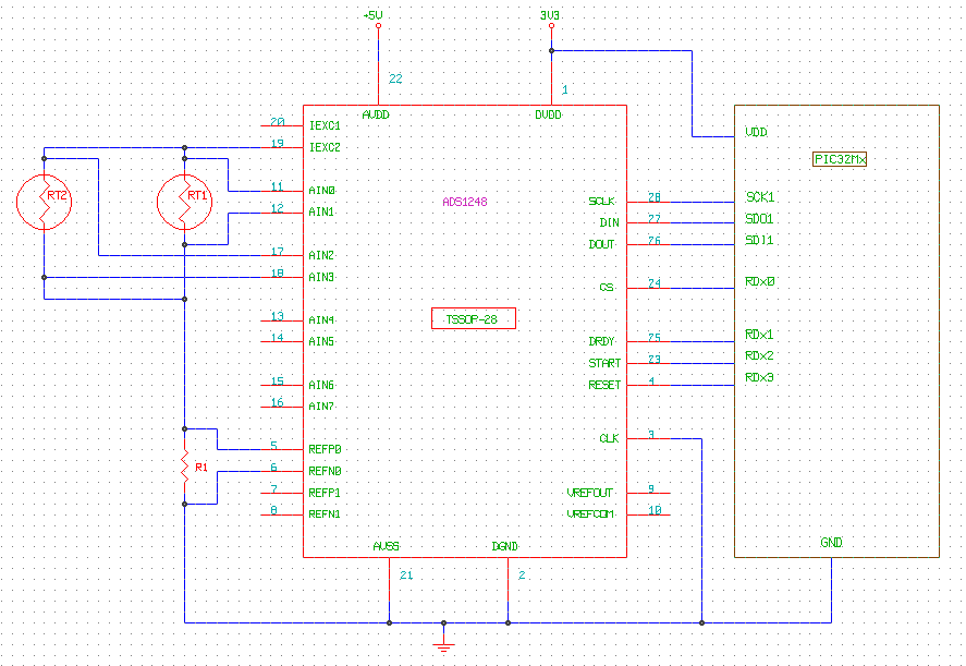
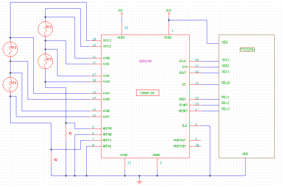
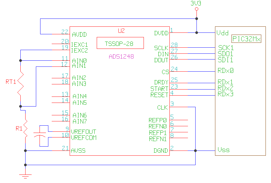
I have just been introduced to the ADS1248 and intend to use it to monitor four 4 wire PT100 in full differential mode. I intend to use the one IDAC to excite 2 PT100s.

I also intend to use the internal oscillator and internal voltage reference hence will not use REFP0,REFN0, REFP1 and REFN1.

Please advice if this setup will work.

I will be using a PIC32Mx CPU on the SPI. See my proposed schematic below.


Regards
Tom

  • Hi Tom,

    One of the benefits of using the external reference is to create a ratiometric measurement.  Doing this type of measurement will reduce noise and drift effects.  What you propose do to is doable if the noise and drift of the IDAC is acceptable.  You will also need to connect VREFCOM to ground.

    You must also make sure that the value of R1 allows for the correct common mode voltage for both RTDs you stack.  You must also make sure that the IDAC compliance is met for the full extent of the temperature ranges you wish to measure.  Using AVDD at 3.3V will restrict you to some degree, especially if you use PGA gain.

    Best regards,

    Bob B

  • Hi Bob,

    Thanks for the reply.

    Drift would definitely be of concern to me. From the reading I have done so far the ratiometric measurement is the best option.

    The data sheet barely touches on this. Might you know a document that explains this principal.

    Could I use figure 4 in the SBAA 180 document as a guide to implement? Its explanation is better.

    The PT100s I intend to measure all have different characteristics, hence I am not sure the same Rbias would work for all.

    Is the option to use a digital pot for Rbias (using the Figure 4 again)?

    You mention using 3.3V for AVDD will limit me. How so? I can adjust it to 5V at this stage.

    Regards,

    Tom

  • Hi Tom,

    SBAA180 is a good place to start, and you will probably want to also take a look at SBAA201.  I've attached an application note to help you better understand ratiometric conversions.

    5852.sbaa110_Understanding_Ratiometric_Conversions.pdf

    As far as input restrictions, there is a voltage compliance for the IDACs where the total voltage developed must be about 1V below the AVDD supply rail.  You can see the effects in Figures 47 and 48 of the datasheet.  The common mode input restrictions are based on PGA gain and must be at least 0.1V from either supply rail.  More information can be found here:

    http://e2e.ti.com/support/data_converters/precision_data_converters/w/design_notes/1370.input-voltage-range-requirements-for-the-ads1248-and-ads1148-families.aspx

    Best regards,

    Bob B

  • Hi Tom,

    in theory (we did not try this configuration yet) attached implementation should work. It might actually be even better to use a separate R_REF2 for the 2nd set of RTD's and connect the R_REF2 to REFP1 and REFN1.
    This high level schematic does not show any input filters. You will have to add them as described in above mentioned application notes.

    You will have to make sure that: (IEXC * R_REF) + 2*(IEXC * RTD@max.temp)  <  (AVDD - 0.7V) to meet the voltage compliance for the current sources.
    And as Bob mentioned you will have to make sure you keep the voltages across the RTD's within the specified common-mode voltage range.

    What temperature range do you need to measure and what current did you want to use for excitation (500uA, 1mA)?
    I could probably come up with suitable values for R_REF and Gain then.

    Regards,

    ADS1248 - 4x 4-wire RTD Application.pdf
  • Hi Bob,

    Thanks for the info on the ratio metric measurement. This is now understood. I have also noted the restrictions on the PGA gain.

    Please see my revised circuit and comment.

    As you can see my circuit opts to connect the PT100's in parallel as oppossed to series as in Joachims suggestion.

    This is because not all will be connected at the same time and would not like a single sensor going faulty interfering with another sensor.

    Regards

    Tom

  • Hi Joachim & Bob,

    Thanks for the reply.

    Yes, I intended to use one IDAC1 current and R_REF1 and IDAC2 current with REF2.

    I will begin the filter issue soon after we are done with the basic connection.

    As you can see my revised circuit is some what similar to youe suggestion but in parallel.

    Whats you take on this?

    My application is a weather station and I will be monitoring Air Temp (0-55DegC), Soil Temp (0-55DegC), Solar and UV radiation usind sensors from

    Kipp & Zonen that use a thermopile sensors.

    I will probably use an excitation current of 500uA but am still working on this. Please advice on your suggested R_REF.

    I will have 2 ads1248 in my application. One will measure differential inputs as in the schematic. The other will measure single ended inputs such as Relative Humidity on a scale of 0V to 1V representing 0% to 100%.

    From a post on this forum, when using single ended input AIN0 to AIN6 would be the Positive and AIN7 would be the common signal is this correct?

    Does this mean the GND for these single ended sensors will not the circuit GND? I will be connecting a temperature sensor such as the LM35 that outputs a voltage of 0V to 0.50V that represents 0DegC to 50DegC and requires 5 - 12V to operate.

    Shall I tie AIN7 to AVSS and DGND for the ads1248 that will monitor sig?

    Please Advice,

    Regards Tom

  • Hi Joachim and Bob,

    The thermopile sensors will be connected as part of the single ended inputs and  not as the differential inputs as I mentioned on the previous post. There output is 0V-15mV.

    Regards Tom

  • Hi Tom,

    as along as there is always only one of two Pt100's connected, your implementation will work. If both Pt100 in parallel are connected at the same time this will not work properly.

    I attached a calculator that you can use to play around with the different PGA, RREF and IDAC settings.
    You need to provide inputs for the yellow cells, the green cells are then calculated automatically. Let me know if you need further help with it.

    There are some nobs that you can turn:
    - If you increase RREF you can potentially use a higher gain, which will yield lower input referred noise.
    - Increasing the IDAC value increases the 'resolution' of the Pt100 as you get more signal out of it at the same temperature. On the other side higher currents lead to more self heating within the Pt100.

    Unfortunately you can not measure single-ended signals when using a single supply (0...5V or 0...3.3V). This is due to the common-mode voltage restriction again.
    You will have to use a bipolar supply (AVDD=+2.5V, AVSS=-2.5V) on your 2nd ADS1248 to implement the single-ended measurements.
    You can then use any input as your negative/common input, which would be 0V (or DGND) in your case.
    There is a tab in the excel spreadsheet where you can input your settings and check if they meet the common-mode voltage requirement.

    Another option is to use the LM7705 to generate a -0.23V supply for AVSS and leave AVDD=3.3V.
    That way you could measure the LM35 and humidity sensor with the PGA set to 1. For the thermopile you should be able to use gains up to 16 if I calculated correct.

    Regards,

    ADS1248 Calculator.xlsx
  • HI Joachim,

    I will go with the series connection of the PT100s as you suggested earlier. See the revised schematic. At some stage I will need to measure a PT1000. I don’t think this will affect the basic setup.

    Thanks for the calculator. I will do the calculations for the values next week and revert.

    With regard to single ended inputs, I think using the LM7705 is the way to go for me now. Thanks for the info.  Some sensors I will use are resistive and vary from 5K to 3M Ohms or 1K to 2K Ohms. To read these sensors do I apply the IDAC current or the Vbais voltage to the selected input? One input will be tied to 0V as you suggested.

    I will work on the filters do and revert with queries if any.

    Regards Tom

  • Hi Tom,

    sounds good to me :-).

    The LM7705 will be most suitable for the single-ended measurements where you will only use gain of 1V/V.
    For higher gains you will have to check in detail if your common-mode voltage requirement is met.

    For the 1-2k Ohm sensor you could employ the same ratiometric setup that you use for measuring the RTD.
    In case you have to connect the lower end to GND and want to use the IDAC for excitation, you should be aware that the absolute accuracy of the IDAC's is not really good as they are primarily meant to be used for ratiometric measurements.

    For the 3M Ohm sensor you will not be able to use the IDAC as even the lowest IDAC setting (50uA) would yield voltages >>3.3V.
    I guess using a voltage divider would be the way to go in this case. You could potentially use the REFOUT for excitation of the resistor string then.

    Regards,

  • HI Joachim,

    I will check that the common mode voltage is meet for the single ended inputs and revert.

    Would it be better to use an external constant current for the 1-2K resistive sensor such as in fig. 6 of sbaa110?

    When using Vbais to bias a single ended resistive sensor, would the other terminal of the sensor be connected to GND?

    Regards,

    Tom

  • Hi Tom,

    I don't understand why you would want to implement this circuit. The ratiometric measurement setup that you use for the RTD's looks simpler and more cost effective to me.

    I am sorry, it is still not 100% clear to me what you try to do with the VBIAS? When you connect one side of the resistor to VBIAS and the other side to GND you will always measure VBIAS back?!?
    I think you will either have to build a precision, very low output current IDAC externally yourself, but easier would be a voltage divider in my opinion.

    Regards,

  • Hi Joachim,
    See my revised schematic attached. Each IDAC will excite a PT100 and its reference.

    The photodiode and thermopile each generate a voltage of 0-15mV. I will use the internal voltage ref. for these. With regard to Vbais, please see

    ·         fig. 5 of SBAA180 and

    ·         example 1 of Input Voltage Range Requirements for the ADS1248 and ADS1148 families”.


    Does it mean that if I applied Vbais (2.5V) to one of the photodiode inputs, I would measure 2.515V at the other input as explained in example 1 above? If this is the case, my questions on this issue are answered.
    For the single ended ads1248 with the LM7705, inputs will be between 0 and 1V utilizing a 1 PGA. With the 24bit precision all should be ok.  With regard to the 3M ohm sensor, the voltage divider fed by REFOUT will work as you suggested.
    Thanks for the calculator. Vcm and other values are calculated easily.
    Regards,
    Tom
  • Hi Tom,

    this looks okay to me. You said you will worry about the filtering later and add it accordingly.

    In case your thermopile and photodiode are free floating and are not connected to any potential then you can use the VBIAS (as shown in the examples you mentioned) to bias the thermopile and photodiode to mid-supply. The voltage generated by the sensor will then sit on top of the VBIAS voltage as you said correctly.

    Regards,

  • Hi Tom,

    I forgot one thing. Please make sure to place a capacitor across pins VREFOUT and VREFCOM as described in the datasheet on p.29.

    Regards,

  • Hi Joachim,

    Thanks for the replies. I will add the cap to VREFOUT.

    On the issue of the filters, I intend add filters to both the asd1248 chips as indicated on the ADS1248EVM board.

    Will this scheme work for both the differential and single ended inputs? I have not really see and notes on the design of these filters.

    I will also begin looking at the registers in detail and possibly revert on another thread.

    Regards,

    Tom

  • Hi Tom,

    The ADS1248EVM input filtering is set up for differential measurements.  The filters are first order RC filters and depending on whether the inputs are differential or single ended the requirements may be slightly different.  In the differential input case you have the cap across the inputs (differential) as the primary cap.  You may or may not need common mode caps (caps from input to ground) as additional filtering.  You must take care that the differential cap is at least 10 times greater in value than the common mode caps otherwise mismatch between the common mode filters can actually create a differential voltage creating error.

    For the single ended case, a differential cap is not needed if the common point is at ground. The similarity between single ended and differential inputs is they both would have a cap from the input to ground (assuming the differential input also has common mode filtering.)  For the differential case you would need to add the cap between the desired inputs to be measured.

    You may be able to use the scheme from the EVM depending on which inputs you will want to measure differentially.

    Best regards,

    Bob B

  • Hi Bob,

    Please have a look at the attached schematic and advice if the connection to AIN7 and VREFCOM are ok. The LM7705 is used to supply Vss with a negative voltage . The first 2 sensors require 12V to operate and I have tied their commons to AIN7 and then to ground. I will use the internal ref.

    With regard to the filtering for the single ended inputs, I intend to put a capacitor on between every (input AIN0 to AIN6) and AIN7. Is this correct for this setup?

    Page29 (INTERNAL VOLTAGE REFRENCE) of the ads1248 mentions that “For stability, VREFCOM must have a path with an impedance of 10Ohms to AC GND nodes such as GND (0V to 5V analog Supply) or AVSS (for +-2.5V analog power supply)…”. Shall I add a capacitor between VREFCOM and AVSS just in case?

    Regards,

    Tom

  • Hi Tom,

    Your schematic appears to be correct.  As far as the connection of VREFCOM you should be ok to connect this to either analog ground or AVSS and should not need the additional capacitor.

    As far as filtering, you should have a resistor in series with inputs AIN0 through AIN6 followed by a cap to ground for each input (as you stated.)

    Best regards,

    Bob B


  • Hi Bob/Joachim,

    Thanks for all you help. I will proceed and complete the design and revert when I have the PCB board.

    Regards,

    Tom