This thread has been locked.

If you have a related question, please click the "Ask a related question" button in the top right corner. The newly created question will be automatically linked to this question.

ADS1299 Supply Problem

Other Parts Discussed in Thread: ADS1299, LM9076

Hello,

I'm using the ADS1299 for biopotential aquisition, after designing and developing a PCB for use with this chip i have encountered an issue i couldn't solve:

I'm using the TPS71750 and TPS71733 for voltage regulation, those are being feed with four AA batteries. When i powered for first time, the voltage at the AA batteries input decreased about 1V, if it was 6V now it is 5V. At the output of the 5V regulator i had 4V and at the output of the 3.3V regulator i had the expected value. I desolded the ADS1299 chip and now the regulations measures are as expected, so i found the issue is in the connection of ADS1299, but after look at datasheet and user guides multiple times i can't find the source of the error.

I think it is maybe in the current requirements of the circuit, each TPS717xx regulator outputs 150 mA, but according to the power consumption of the ADS1299 this is above the needed. 

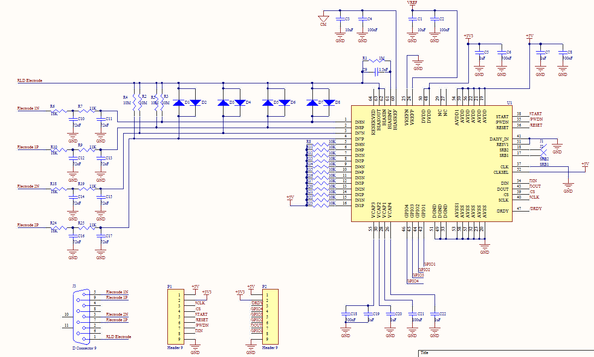
This is the schematic of the ADS1299 adjustment circuit i have made, please let me know if there is an error making this uncomfortable phenomena to happen.
Best regards,

Julián

:)

  • I realized that when I run those tests I haven't take into account the Power-Up sequencing. So, there are several function pins floating, as /PWDN, RESET, etc. 

    Could this one really be the problem?

    The datasheet recommends all pins active low during power-up, I could test this by connect all pins to GND or should I create a basic test program at the control MCU (witch is in another board and works perfectly)?

    I'll let you all know if this work, but if there are any other suggestions about this malfunction issue I will really appreciate it

    Regards,

    Julián

    :)

  • I just tested with all the IO pins grounded and with a sample program making the Power-Up sequence. The circuit still not working.... If it is nor current nor IO pins configuration, which could be the problem? I already check every little connection in the circuit and are all as the schematic, must be a design problem!. I really don't know what to do here, the connection seems legit according to the ADS1299EEG-PK User Guide.

    PLEASE HELP!!!

    The ADS1299 IC is getting very hot, how could i test the IC to let me know if it is working properly?

    I'm desperate here...

  • Did you solve the heating problem, or did you get an answer?

  • No :'(

    Do you have a similar problem?

  • Not yet. I just started to work with the ADS1299 and the EVM Board.

    I thought before getting intro trouble i look what problems could arise and what solutions are discovered.

    Maybe it helps to restart and do a new Post with your heating problem.

  • Hello Julián,


    you didn't connected pin 31 (RESV1) to the GND. You must connect this pin to the GND, but this is not the problem with overheating the ADS1299. ADS1299 package is very difficult for soldering, you must check all soldered pins under microscope or some lense if maybe have a bad connection. I think that this could be the problem. ADS1299 must work without MCU and it will not drop the voltage of the power supply.


    Regards,

    Vojin

  • Hello Vojin,

    Thanks for your answer.. Currently the pin 31 (RESV1) is connected to ground, as shown in the schematic of the first post. And I already carefully revised every connection of the ADS1299 to be properly connected to the PCB. Even though i can get to the problem, i don't know what is causing this error.

    Currently I'm building a more basic circuit on breadboard just to check the configuration pins, I think maybe the problem could be related with the pin 52 (CLKSEL) which is connected directly to 5V. Two possible errors i have think of; the digital circuit is tied to 3.3V and the clock select circuitry makes part of this and should be tied also to 3.3V, and the other one is that should include a 10kOhm pull up resistor, not be connected directly. I decided this connection because i'm planning to use the internal clock of the chip.

    Vojin, please let me know what do you think of this. If you can, show me an example of a basic circuit connection (without MCU) just to test if the chip is working correctly.

    Again, thank you very much.

    The best regards,

    Julián.

  • Hi Julian,

    yes, you should tie the CLKSEL pin to DVDD and not AVDD, but in my opinion you don't need a pull up resistor, it's a simple digital input.

    It's obvious that the battery voltage drops because of high load, and when the LDO has only 5V input voltage it cannot produce 5V at the output anymore. Your LDO needs a input voltage of at least 5.17V (see note 1 on page 3 of datasheet), that is 1.29V per cell. Your battery voltage will drop very quickly under 1.29V per cell, so you will have to replace them quite often. I'm using the LM9076 (for 3.3V and 5V) together with 5 NiMH cells. In general, rechargeable cells stay at a voltage of 1.2V during a wide range of discharge (but of course don't forget they have 1.5V when fully charged, but the LM9076 can handle this). So with 5*1.2V=6V I have enough input voltage for the LDO for a longer period. I know the datasheet says you can use 4AA batteries, but in my opinion this isn't very useful.

    Good luck for your project,

    - Andreas

  • Hi Julian,


    the connection of the CLKSEL pin could be the reason of the voltage drop of battery power supply, because CLKSEL is the digital input with max input voltage of the 3.3V. With connection of the 5V, you could demage the ADS1299 and because of this voltage it can overheat. Try to disconnect this pin, and after that check voltage drop of the battery. If it still exist, maybe you demaged the digital part of the device.


    Regards,

    Vojin