This thread has been locked.

If you have a related question, please click the "Ask a related question" button in the top right corner. The newly created question will be automatically linked to this question.

ADS1299, 4 electrodes, basic eeg, bias drive

Other Parts Discussed in Thread: REF5025, LM9076, ADS1299, ADS1278

Hi everyone!

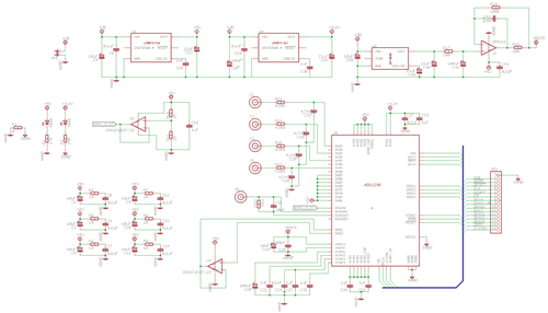
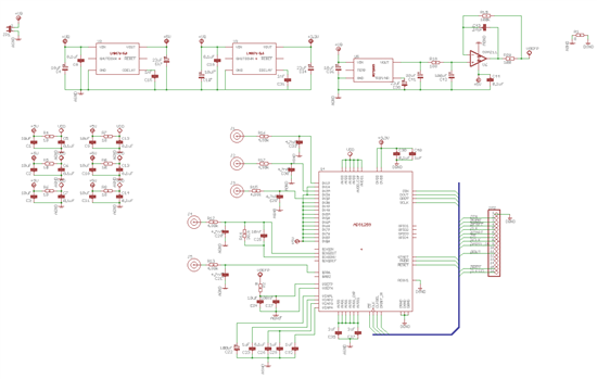
I'm currently working on a schematic for a basic eeg-application (brain-computer interface) with an ADS1299, see picture below. I have two unipolar supplies (+5V analog, +3.3V digital, LM9076). I'm using a REF5025 2.5V Voltage Reference for the ADC. I have 4 Ag/AgCl electrodes (just simple ones, no shielding) and I want to use two of them as signal electrodes. One electrode should act as a reference (routed to negative input pins via SRB1) and I would like to use the Bias Drive. I have read the Documentation for the ADS1299 Demo kit and also the appnote sbaa188.pdf about improving CMR. But I still haven't figured out how to deal with the Bias Drive in my setup.

As I have seen on page 59 of the ADS1299 datasheet, I need seperate BIASOUT and BIASIN electrodes (that means, I would would need a fifth electrode). A basic question about the Bias Drive: When I use the internal mid-supply option (that is 2.5V), the BIASIN senses the current common mode voltage and via the BIASOUT electrode the ADS1299 will drive the body until the common mode voltage reaches BIASREF? Why do I need other electrodes for Bias sensing then? Like it's stated in the first two codelines for the Bias drive on page 5:

WREG BIAS_SENSP 07h // Select channel 1—3 P-side for bias sensing

WREG BIAS_SENSN 07h // Select channel 1—3 N-side for bias sensing

How are the electrodes (especially the BIASOUT electrode) connected to the body? Just a 5k protection resistor or with additional capacitors like in the schematic below? By the way, on the schematic there's still the BIAS_ELEC connected to BIASIN, I would leave that input open and select one of the above electrodes via the input mux as bias electrode of course.

If a low-frequency common mode voltage is coupled into the body, the feedback loop will take care about it, right? So when the common mode voltage is set properly, the every ADC will measure 0V (in the best case of course)?

What do you think about an additional highpass at every input? I would set the cut-off frequency at around 1Hz to get rid of DC-part and very slow brain waves. I'm interested in sensomotoric waves, e.g. thinking of a arm or leg movement.

Maybe I don't need a bias drive? I'm not sure if I get another electrode, so I could go with the option of two differential amplifiers then. But I would need a bipolar supply for the differential version, right?

I hope you guys can help me, I'm really stuck here right now.


greetings,
Andreas


  • **TI EDIT February 20th 2019; FOR GENERAL ADS129x ASSISTANCE, PLEASE SEE NEW BIOPOTENTIAL FAQ LOCATED HERE**

    Hello everyone!

    Sorry for offtop. I would appreiciate if someone tells me what program what programm was used to draw the scheme above

  • Hey Andreas,

    did you find a solution by yourself, or did you find some useful information for Single Ended EEG. Especially the connection of the Bias and Reference Electrode is an information, that is not clear in the user´s guide.

    Regards

    Melanie Jung

  • I'm using EAGLE (http://www.cadsoftusa.com/). You can download the free Light edition, the only limitations you have then will be a limited board area of 100x80mm, two layers, and only one sheet in the schematic editor, that's it. I'm also using the light edition and I'm doing perfectly fine with it.

    About the Single-Ended EEG: I figured it out how it works (at least I think I do, haven't tried it yet). You have to connect the R-C-network between BIASOUT and BIASINV, you can leave BIASIN open, if you use a dedicated bias drive electrode (J4). You could use the BIASIN input for selecting any of the other electrodes to be used as bias drive electrode (via registers) and you have to connect the BIASIN pin to BIASOUT then.

    Also I'm using a dedicated reference electrode (J5), that is routed to every negative input pin of the pga's. This is how the bias drive works (look at fig. 47 on page 49 in the ADS1299 datasheet): You can select several channels via the BIAS_SENSP/_SENSN switches to generate the current commode mode voltage. This is then feeded into the bias amplifier, that is part of the closed bias feedback loop. The amplifier will then reduce the common mode voltage via the bias drive electrode.

    I will not use seperate highpass filters at every input, this might increase noise on the inputs, and I definately do not want that.

    I'm still working on the schematic, because I will also need a bus transceiver to enable the ADS1299 to communicate with the 5V microcontroller pins.

    If anybody knows how to improve my schematic, please let me know!

  • Thank you for the information.

    I try it and will let you know if it works.

    Regards

    Melanie

  • Thank you very much, Andreas!

    Good luck in your search.

  • Hi Andreas,

    for four channel EEG you need four INP inputs of the ADS1299 for EEG signal measurement, for example you can use INP1, INP2, INp3 and INP4. For reference electrode you cannot use SRB pins, because they are not routed directly to the amplifiers input. The better solution is to short-circuit INM inputs (INM1, INM2, INM3 and INM4) and this connection use as reference electrode.

    Because EEG signal amplitude is small, about 10uV, you must use RDL circuit for bias drive. On the schematic that you posted, use only BIAS_OUT pin of the ADS1299 and connect it to the parallel RC network R12 C22, without connection to the BIAS_INV. In this way you have open-loop amplifier in the feed-back loop of the first stage of the instrumentation amplifier. With this connection you can reach CMRR of about 140dB. I've tried this, and I've got fantastic signal quality. Net name BIAS_ELEC, you dond need, and also you dont need U2.

    Another very important thing is that you must use battery power supply, or if you use USB or some wall adapter, use isolation DC/DC converter for patient safety and for better CMRR performance.

    Regards,

    Vojin

  • Thanks for your answer, Vojin!

    Figure 19 on page 16 of the ADS1299 datasheet shows, that you can route the signal from SRB1 to PGAN, so why do I have to connect all the negative input pins directly to the reference electrode? (And I guess by INM1-INM4 you mean IN1N-IN4N?)

    Yes, I have already seen that I don't need the BIAS_ELEC signal. But why do you say I don't need U2? It's the 5V voltage regulator, I'm using for the battery supply.

    And what is the purpose of using a open-loop amplifier? I thought I have to create a closed RLD-loop?

  • Hi Andreas,

    I didn't mean U2. You dont need U3. The SRBx lines are used to allow you to route a common signal to all the inputs. One thing to keep in mind is that when you do this, you are going to have mismatching between your (+) and (-) inputs which may cause a higher 50/60Hz component to show.

    For RLD amplifier, it is open loop amplifier in closed loop. The loop is closed trough the IN1P - IN4P amplifiers. It is very complicated to explain this now. I'm currently writing science paper about this RLD configuration, but belive me, it work 1000 times better than conventional RLD circuit.

    Regards,

    Vojin

  • Ok, yes the U3 opamp was in the old schematic anyway. I have already removed it in the newer schematic in my second post.

    But I still don't get your point. First, why is there a mismatch between (+) and (-) inputs when I connect the reference electrode via the SRB1 pin to the negative PGA inputs instead of connecting them directly to INxN? In my opinion this is the exact same connection. And second, do you mean the feedback loop is closed via a path over the bias electrode to the INxP electrodes? I don't completely understand the way this feedback loop will work the way you describe it, but I need a good reason to explain why I chose this type of connection.

    Thanks for your support by the way!

  • Hello Vojin,

    what means RLD? Is your paper IEEE? When will it be published?

    I really do not understand why it is better to route the same Signal to the negative input pins than via SRB1 to the Comparator.

    Regards Melanie

  • Melanie Jung said:
    what means RLD?

    RLD means Right Leg Drive. It's a feature to improve CMRR by driving your body actively via a seperate electrode.

    I have another question:  I want to drive some LEDs with the GPIO ports, but I don't find anything about these ports in the datasheet. It only says "digital inputs/outputs", what means that it can drive up to +/-10uA. But that's not enough for driving a BC856/857 into saturation, when I'm using a 2mA LED or so. What kind of outputs are these ports? Open-drain?

  • Hello Vojin!

    Okay, to sum up:

    The reference Signal is fed to all negative inputs of the channels 1-8, and the sensing EEG electrodes to the positive.

    The Bias Signal is generated by using the internal (or external) bias reference with setting register BIASREF_INT=1 (BIASREF_INT=0) and compare it with the internal BIAS_AMP with the electrode DC signals of all inputs (positive and negative). The signal from th input is routed to the BIAS_AMP by setting the register entries BIAS_SENS[x]=1. The output of the amplifier BIASOUT should then be connected with the bias electrode that is used to set the patient to a defined potential.

    IS that correct or did i miss something.

    But what is the RC part of 1 MOhm and 1.5 nF in Figure 46 of page 48 int he ADS1299 datasheet for?

    Regards Melanie

  • Hi Melanie,

    everithing that you sy is correct. About that value you asked, you can put that values. I dont solder that components and I've got better rejection of the common mode signal.

    Regards,

    Vojin

  • Did you measure with EEG patient cables or only the chip to get to a result of 140dBm?

    At the moment with the measurement equipment of DIN EN 60601-2-26 for the CMMR test i only get about 90 dBm with the RC in my bias loop and the shortest patiente connection available (12"). There is a huge dependency of the CMRR on input cable length, did you also think so?

    Regards Melanie

  • Things about BIAS-Drive have cleared up for me now, thanks guys! One thing that's still unanswered for me is the problem of driving LEDs with the GPIO pins. I posted it in the logic forum: http://e2e.ti.com/support/logic/f/151/t/273763.aspx

    best regards,
    Andreas

  • Hi Melanie,

    I measured CMRR of 140dB with EEG patient cable. I also measured CMRR with RC components in the patient bias drive loop, and I've got similar results as you. After that I've removed that two components (RC from the feed-back loop) and I've measured CMRR of 140dB. I've also tried to record real EEG data with that configuration and I've got fantastic results. I'ts amazing.

    Try to remove RC and measure CMRR.

    Regards,

    Vojin

  • Hi Vojin

    Also do I need filters before or just with low gain (<24) and limiting SPS's (500sps for example) of the ads1299 is enough to avoid more IC's?

    Thank you

    Regards

    Felipe

  • Hi,


    This may be off-topic but I wanted to know where I can find the eagle cad library containing the ADS1299. I downloaded a TI library which contained other ADS chips but not the 1299.

    Would really appreciate any pointers!

    Best regards,

    Tamer

  • Hi Tamer, I worked with ADS1278 which has the same cad design that ADS1299

    Regards.

    Felipe

  • Hi Felipe,


    Thank you. Much appreciated!


    Regards,

    Tamer

  • Can anyone plz suggest me that what headset or how many number of electrodes i should use to interface with ads1299..?

    to read movement related cortical potential

  • Hey Vojin,

    it seems like the folks over at OpenBCI followed your advice on generating the bias signal in Version 3 of their EEG board. They removed the RC feedback from BIAS_OUT to BIAS_INV. Instead they feed the BIAS_OUT signal through a parallel RC circuit into the electrode just like you suggested. I wonder why this method to generate the bias signal is not adopted in the official TI docs for the ADS1299 if it is superior with respect to CMRR.

    RS

  • Hi Vojin,

    I'm very interested in your setup, it sounds great! I'd like to reproduce that. From reading this thread, it sounds like the setup is:

    - the sensing electrodes are connected to positive inputs of all channels
    - negative inputs of all channels are shorted together. are they connected to anything?
    - BIASOUT is connected to bias electrode
    - BIASINV is not connected to anything; no RC network between BIASOUT and BIASINV
    - BIASREF_INT=1, BIAS_SENSP=1 for all channels. is BIAS_SENSN=1 also?

    Thanks for clarifying this, it is awesome.

    P.S. Did you publish your paper on this yet?

    Best,
    Alex