Is it possible to run the AFE4400 on a buffered clock input rather than an external XTAL?
This thread has been locked.
If you have a related question, please click the "Ask a related question" button in the top right corner. The newly created question will be automatically linked to this question.
Yes it is possible to connect a buffered clock input on the Xin pin of AFE4400. This requires that XTALDIS (bit 9) CONTROL2 Register (Reg 0x23h) is set to HIGH.
The AFE4400 has been characterized for 8MHz frequency only. Running at higher clock frequency will likely affect the ADC in the receive signal chain and impact the performance adversely.
For a small size crystal, our recommendation is the 8MHz Piezo Ceramic resonator crystal (CSTCE8M00G55-R0) which has the following dimensions (1.3 x 3.2 x 0.7mm)
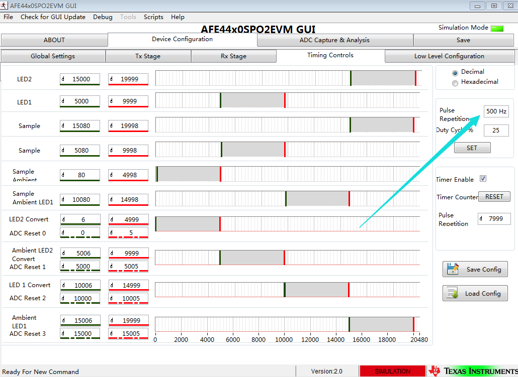
The configuration just like below :
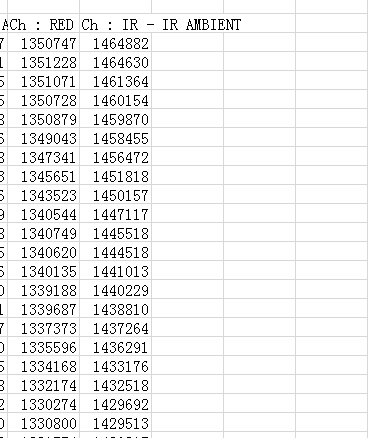
I save the data by the GUI:
By this picture ,we can find the data of (IR-IR AMBIEMT) is Seven digits ,by the formula :data*1.2/2^21,we can get the voltage is about 0.7v-0.8v, that right.
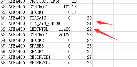
This is the Register configuration of 21h and 22h .
In order to separate from AFE44x0spo2EVM GUI ,I need to configurate Register of 21h and 22h to mcu software which offer by TI. I configurate Register of 21h and 22h juest like below:
However, I get the signal data of (IR-IR AMBIEMT) and (R-R AMBIEMT)are 6 digits! by the formula :data*1.2/2^21,I can get the voltage is so small , that wrong. But I do not know where I have done wrong. Configurating register of 21h and 22h to mcu software is right?
sorry to bother you. Looking forward to your answer, Thank you very much!
Best regards.
XLL
Hellow Praveen Aroul:
My testboard is similar to the AFE4400EVM, I have connected the transmissive finger clip pulseox sensor to my board and I can get the signal by AFE44X0spo2EVM, then I want to configure AFE4400 by MCU software instead of AFE44X0spo2EVM ,but I can get the signal is smaller than the signal which I got by AFE44X0spo2EVM. I configure AFE4400 by MCU software according to I configure AFE4400 by AFE44X0spo2EVM. So I think the reason is that I fail to configure AFE4400 by MCU software.
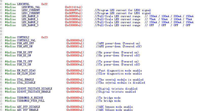
I find the example code,the code definite the register just like below:
if I want to change the walve of 0x22 register bu MCU softwave, what are the steps?
Thank you very much.
XLL,
If PRF is set to 500hz, it is the sampling rate of the IR(or RED).
Refer to the Section 8.3 in the AFE4400 datasheet for a more detailed understanding of the device and the timing engine.