

I am having trouble controlling the DAC 5687 chip on DAC 5687 EVM board. I need help to set up the EVM board so that analog output changes proportionally to the digital input I enter.
Following are the four approaches I had tried:
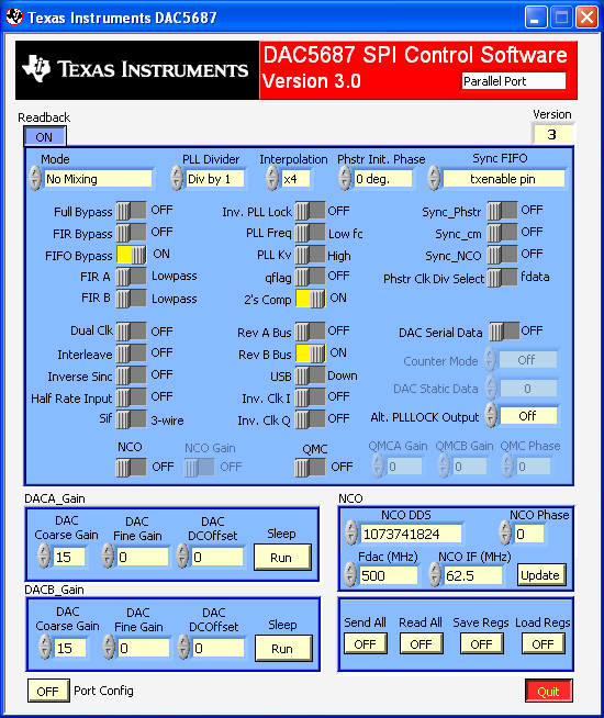
1. I have verified the data that I wrote to the EVM board correctly at RP5, 6, 9 and 10. I am writing at the data rate of 16 Mhz. When I write 0x0 to the DAC and both of the analog output of Channels A and B show 0. However, I cannot tell the difference of the analog output when writing 0x7FFF7FFF to the DAC. I write other non-zero values. Also show the same thing. (I cannot tell the difference.) I am hooking up the clock with my source clock, which runs at 84 Mhz. What could be wrong? Do I need a faster input clock? How fast? I have verified the 1.8 V and 3.3 V power supply to the board correctly. I used SPI control software from TI to turn on FULL/FIR/FIFO Bypass only.
2. For DAC 5687 setup, I only turned ON FIR/FIFO Bypass but leave NCO and the rest OFF. The interesting thing is the analog output is not proportional to the digital input I set. For example, I write a 32-bit 0x7FFF7FFF (i.e. A=0x7FFF, B=0x7FFF). The analog output is not half of the analog output when I write a 32-bit 0xFFFFFFFF. The clock rate to CLK2 is 82 Mhz. The CLK1 was left unconnected. The clock input is from my CPU board (3.3 V). I am writing 32-bit DAC words at 27 Mhz. The DAC 5687 EVM was applied with 1.8 V and 3.3 V respectively. After connecting the power cord, I have confirmed with the meter on J7 and J10 again. What is the configuration that I have to set through TI DAC5687 SPI Control software to get it right?
3. To isolate the problem, we built a test board with switches connected directly to the DAC 5687 EVM board. The switches are used to emulate we are sending different digital values to J13 and J14. 16 bits for each J13 and another 16 bits for J14. No matter what we changed digital inputs through the switches or disconnect the switches, the analog output remains the same (like noise). If we turn off NCO, analog output stays 0 all the time. Do we need to turn on NCO while writing digital values to the EVM board. Could this be a defect on the DAC5687 EVM board?
4. We use bypass (no FIFO, no FIR). We can provide external square clock at 2 Mhz, 41 Mz and 82 Mhz through J4 CLK2. How do we set up the evaluation board so that the analog outputs from J5 and j9 change proportionally to the digital inputs through J13 and J14? In addition to connecting our development board to the EVM, we have also tried to directly connect an external test board with dip switches to the EVM. With either one of these two approaches, nothing change on the analog output side.
Thanks,
Jew-Dong Kuo

-
Ask a related question
What is a related question?A related question is a question created from another question. When the related question is created, it will be automatically linked to the original question.

