This thread has been locked.

If you have a related question, please click the "Ask a related question" button in the top right corner. The newly created question will be automatically linked to this question.

ADS131 Fault Detection

Other Parts Discussed in Thread: ADS131E08

Hello,

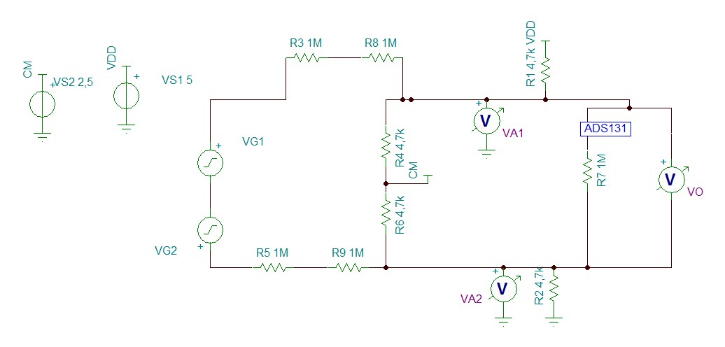
I am currently working on a circuit using ADS131E08. For now I am only using 3 inputs for voltage sensing, following the differential set up shown in the datasheet (under "VOLTAGE SENSING"). It works as expected, but I need now to use the fault detection features, to detect that the "L" probe, for example, has been disconnected. Under "FAULT DETECTION" in the datasheet there is a suggestion to use pull up and pull down resistors to trip the signal when the circuit is open. Problem is, when using the topology suggested in the mentioned section, the fault detection messes the signal, and doesn't actually trip the signal because it only makes a resistive network  between AVDD and OPAMPOUT. Could you please help me? As mentioned, I am using EXACTLY the same topology as suggested on the datasheet, but I simply cannot get fault detection to work, what am I missing?

Thank you very much in advance.

  • Have you seen the "Fault Detection" section/circuit on page 48 of the datasheet?  If the circuit is similar, you may need to tweak the threshold setting in the FAULT configuration register (address 0x04).  If all appears to be right, can you share your schematic/configuration of the input circuit?

  • Hello, this is the circuit.

    R1 and R2 are the pull resistors mentioned in the datasheet. But they are messing up with the differential signal. If I change their values, the divider with R6 and R4 will change the signal offset, but I simply cannot make a good signal oscillate around CM and having a bad signal trip to VDD or GND.

  • From the looks of your circuit, is it a safe assumption that you are operating the ADC with single supply (AVDD=X and AVSS=0(GND))?  Or are you running split supply?

    Additionally, the R5, R9, and R6 resistors usually aren't used.  There is strictly a voltage divider on the line voltage side and not the neutral side.  Depending on your supply configuration, the CM point on your schematic would have neutral connected or CM (as you have it configured).

  • Yes the ADC uses 0,+5V source.

    This is the example circuit from the datasheet. Dividing the neutral, I imagine, is for safety purposes.

    Anyhow, the circuit works perfectly, my problem is with the fault detection part: R1 and R2, without them I'm good but I can't get fault detections, with them, my signal gets bad..

  • You are correct with respect to the pull-up/pull-down resistors shown in the datasheet.  For your application, they will probably not work and the information provided needs to be reviewed.

    The Fault Detection function of the ADS131E08 is really intended to detect and alert for input signals that exceed the threshold limits.  Due to the voltage divider used in sensing the line voltage, the pull-up/down resistors do not allow for open-circuit type detection (as you noted the input signal doesn't exceed the threshold).

    Regarding the previously mentioned "extra" resistor, it is normally excluded (as shown in Figure 43).