This thread has been locked.

If you have a related question, please click the "Ask a related question" button in the top right corner. The newly created question will be automatically linked to this question.

ADS1299

Other Parts Discussed in Thread: ADS1299

Hello,

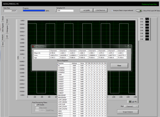
I would like to use ADS1299 for EEG amplifier. I bought its evaluation kit, seems work perfect. Based on that and my requirements, i designed a PCB and i made two systems based on ADS1299. One of them works perfect, but the other one no. To make a test, i put the first channel on test signal; here are the related parameters and configuration registers:
- VREFP: internal, 4.5V
- VREFN: GND
- AVDD: +5V
- AVSS: GND
- DVDD: 3.3V
- CONFIG1: 0b10010110, osc: 2097152Hz so sample rate = 256
- CONFIG2: 0b11010000, test signal freq= 1Hz, amp: 1 * ( 4.5 – 0 ) / 2.4 mv
- CH1SET: 0b01100101, channel 1 on test signal, PGA gain = 24

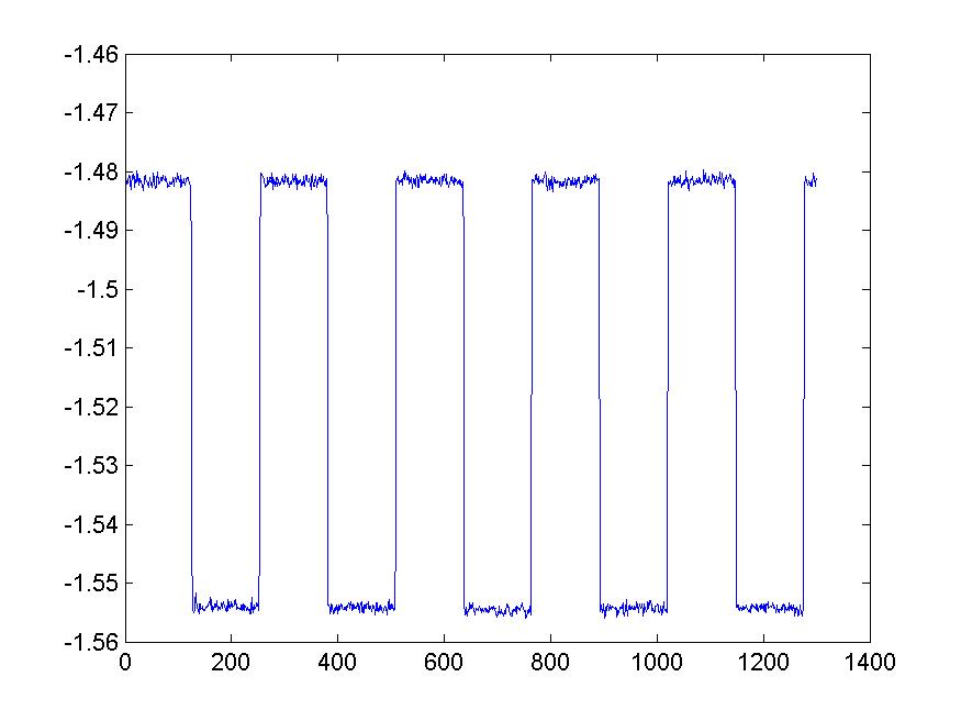
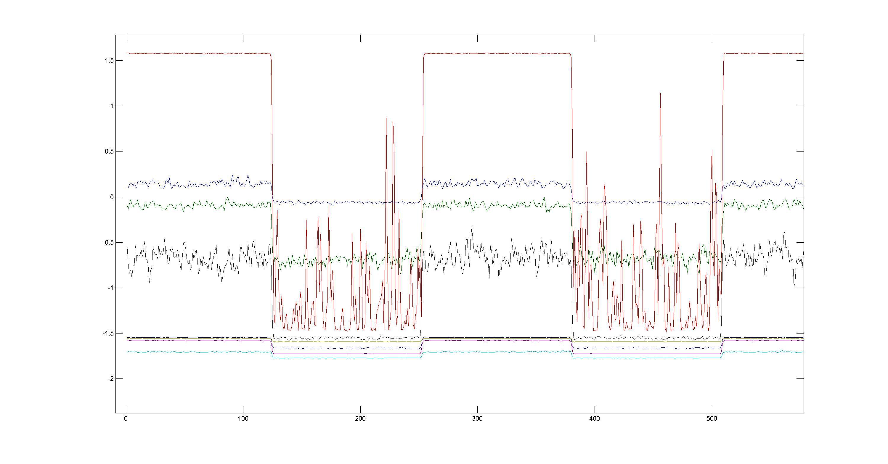
So according to these configurations, I should have a 1Hz square wave with +-22.5v amplitude. I have this in one of my PCBs but in the other on the amplitude is not correct, the wave form is noisy and it is shifted down (you can find the ch1 output on the attached pic).
For me most probably it is related to hardware, but both boards are the same. Do you have some idea about this problem, concerning to the output signal, it can steam from with part ?

Thanks in advance

  • Hi Javad,

    Your configuration settings and calculations seem to be exactly right. The only mistake that I've noticed is the Test Signal amplitude. The CONFIG2 settings you show produce an amplitude of 1.875 mV (that's +/- 1.875 mV or 3.75 mVpp). Following PGA = 24, the resulting Test Signal should be +/- 45 mV (90 mVpp).

    I've configured the ADS1299EVM as you seem to have done, and my Test Signal on Channel 1 measures 3.74 mVpp before the PGA.

    However, I am still puzzled by the image you are showing. Can you tell me what the scale on the Y-axis is (mV or V)? Are you measuring the data after it is gained by the PGA?

    I would also double-check your AVDD, AVSS, and VREF on your boards, just to be sure. That fact that your waveform shows only 0.075 (mVpp or Vpp) is concerning, perhaps one of your inputs is saturating.

    Regards,

  • Hi Ryan,

    Thanks for your reply,

    I have checked again AVDD, AVSS, and VREF, they are +4.99V, GND and 4.49V sequentially. The vertical axis of my figure is in Volt.

    For me several points are really strange:
    1- Except the amplitude which is not correct (as you said), why the waveform is shifted down? In your case, it is symmetric around GND (zero DC), but in my waveform, it has a negative DC value.
    2- Why the waveform is too noisy?
    3- From datasheet, I understood that if we put a channel on test signal measurement, and this test signal generated internally, so the output will be independent from nearly everything e.g. input pins offset, SRB1 and SRB2 switches, etc. just the PGA gain will be important and the amplitude and frequency of internally-generated test signal. Am I right? If yes, why it could not be saturated, because it is independent from input pins.

    thanks in advance

  • Hi Ryan,

    I have put all the channels on test signal mode with PGA gain of 24, here you can see the results. Same as before, the "y" axis is in volt. Every things are not correct except frequency !!!