This thread has been locked.

If you have a related question, please click the "Ask a related question" button in the top right corner. The newly created question will be automatically linked to this question.

Analog signal quality problem above 10 HZ in DAC8568

Other Parts Discussed in Thread: DAC8568

Hello All,

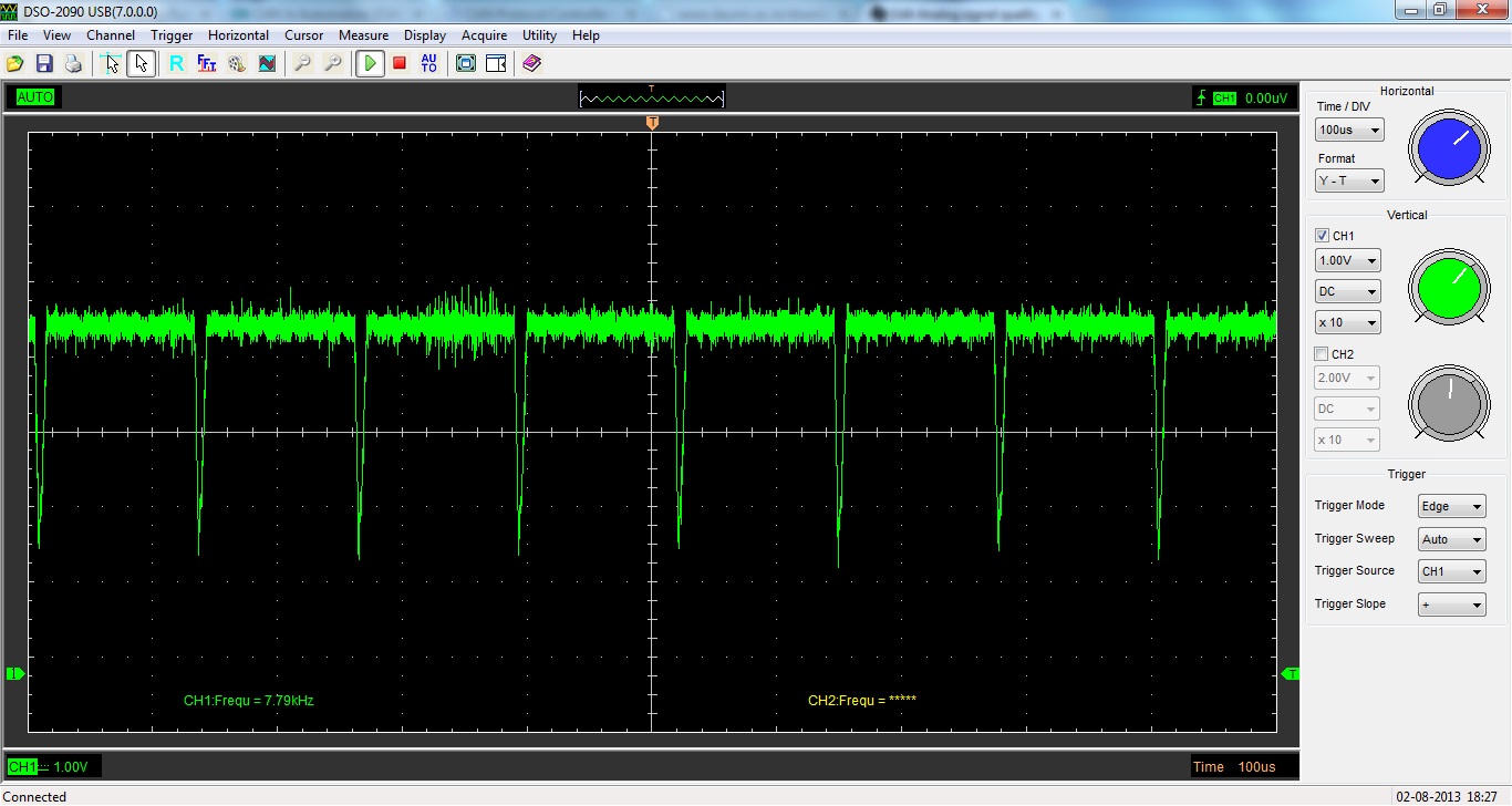
I hope you all doing good. I am using DAC8568 and i am able to get this IC working. I am generating sine wave (by using digital data) and able to see that data also at the output. If the frequency of sine wave is <= 10 HZ the waveform seems to be fine and quality is also good. If i cross above 10 HZ (analog output frequency) glitches are observed in the analog output. Can you please help me out to solve this problem?

  • Mahesh,

    Can you provide a scope capture of this transient?

  • Hello Kevin,

    I think i have sorted out the root cause but i am unable to solve it.

    I am writing the data as 0xFFFF and 0x0000 to the channel 0 continuously  at the rate of 4 Khz.

    But analog out put is not changing according to that. Sometimes it is updating and most of the time data is getting ignored.

    The analog output (Square waveform )frequency observed on CRO is 1.29 KHZ.

    For your reference i am attaching the simulation waveform(On hardware also behavior is same). I am using 27 MHz clock for the interface. 

    The Signal Names are as follows:

    SCLK      -->    clk_i (27 MHz),

    SYNC     -->    sync_o,

    LDAC      -->    ldac_o,

    DIN         -->    data_o

  • Hello Mahesh,

    Do you happen to have the scope captures of the analog output where you are measuring the update frequency?

    I will be trying to replicate this behavior to see if we can figure out what is going on.

    Also, would you happen to have a schematic of the setup you are using? 

  • Hello Mejia,

    I think there was parallel data settling time problem. Frequency upto 200 HZ analog waveform is proper above that steps are coming in the analog output.But i need one more suggestion to use software LDAC function.

    I want 4 DAC output. So i need to write it for all the 4 channels.

    First i will write data to particular channel using SYNC contrpol pin (making it as low) and then ll send software LDAC data. is this right? 

    1st channel = X"0308000F";     --- 2.5 V

    2nd channel = X"0340000F";    ---1.25 V

    3rd channel = X"032BFFFF";    --- 3.5 V

    4th channel = X"033FFFFF";    ---- 5 V

    Then I am sending software LDAC 

    Data              = X"03FFFFFF";

    For your reference i am attaching the timing diagram. 

    I am writing these data' s @ 7.8Khz rate. So i should get constant voltage at the output but analog waveform is varying like as follows

    Can you please suggest me to solve this issue?

    Regards,

    Mahesh Hegde.

  • Hello Mahesh,

    Mahesh Hegde said:

    Then I am sending software LDAC 

    Data              = X"03FFFFFF";

    The code that you are using for LDAC is actually writing and updating all the values to full scale (5V). This is probably the reason why your output kept switching back to full scale.

    You can set software LDAC for each channel, but you need to toggle it HIGH and LOW manually.

    There is no single code to update all channels without writing to a channel in the same code, but there are a few alternatives.


    Mahesh Hegde said:

    1st channel = X"0308000F";     --- 2.5 V

    2nd channel = X"0340000F";    ---1.25 V

    3rd channel = X"032BFFFF";    --- 3.5 V

    4th channel = X"033FFFFF";    ---- 5 V


    The control bits that you are sending (0xd3dddddd) are for "Write and Update" meaning that the software LDAC is being triggered for each channel immediately after writing to them. If you use this control, a separate LDAC code is not necessary.

    If what you are trying to accomplish is to write all the registers first, and then trigger them all to update at the same time. Let me suggest the following.

    First tie LDAC to HIGH.

    Then you should use the "Write Only" control bits (0xd0dddddd) (DAC8568 Datasheet, Page 38) for the first 3 channels.

    For the 4th channel you should use the "Write One Channel and Update All" (0xd2dddddd) (DAC8568 Datasheet, Page 39).

    As an example using the codes that you used it would look something like this:

    1st Channel = 0x0008000F      -     2.5V         (Write Channel 1)

    2nd Channel = 0x0014000F     -     1.25V       (Write Channel 2)

    3rd Channel = 0x002BFFFF     -     3.5V         (Write Channel 3)

    4th Channel = 0x023FFFFF     -     5V            (Write Channel 4, and Update All Channels)

    Let me know if this resolves your issue.

  • Also I just wanted to correct a typo just in case anyone else is trying to use the "Write and Update".

    Mahesh Hegde said:
    2nd channel = X"0340000F";    ---1.25 V

    It should be : 2nd channel = X"0314000F"

  • Hello Mejia,

    Thanks for your reply. I have got it working for 4 channels & LDAC is tied low. I had followed the below procedure.

    1.X”0608000F”

    2.X”0308000F”

    3.X”0314000F”

    4.X”032BFFFF”

    5.X”033FFFFF”

    These 5 values are written serially using SYNC. I have checked the analog output by sending the sine wave on all the 4 channels with different frequency.

    But steps are found above 300 HZ. quality of waveform(steps are observed in the analog output) is not good in high frequency. How i can get smooth waveform?

    The video is attached here in the below mentioned link.

    https://e2e.ti.com/cfs-file.ashx/__key/communityserver-discussions-components-files/73/6082.analog_5F00_output_5F00_upto500HZ.rar

  • Hi Mahesh,

    I have  a few questions to better assist you with your issue.

    • Could you explain your application?
    • What is your Vref?
    • What is the target frequency of the sine wave?
    • What is the target resolution of the sine wave?
    • What is the procedure that you are following to create a sine wave on a single channel?
  • Hi Mejia,

    Vref for the DAC is 2.43V. 

    I will get back to you regarding this issue after sometime. I am suspecting the problem in my parallel data itself(sine wave generation).

    Upto 100 Hz analog waveform seems to be proper with single channel, after that i can observe the small small steps in the sine (analog)waveform.

    I will check thoroughly and ll let you know with all the inputs.

  • Hi Mahesh,

    Just let me know if you need anything else.

  • Hello,

     Did you ever solve the problem? I am also facing the same issue, when the frequency of output waveform I am getting exceeds around 100Hz the waveform becomes not smooth ie I can see steps in waveform. Please send me the solution if you have found one.

    With regards

    Shalini