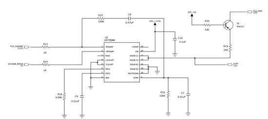
Hi,I am currently using UC1524A PWM IC in my project. I understand the duty cycle of output is changed with respect to the output of the Error Amplifier ie PIN 9(COMP).
In this circuit, Pls explain the change in PIN9 (COMP) voltage with the Input VOLTAGE_ERROR (0 or 5V signal) and FLD_CURRENT is (0 to 5v varying signal).


