This thread has been locked.

If you have a related question, please click the "Ask a related question" button in the top right corner. The newly created question will be automatically linked to this question.

ADS1248 IDAC and REF problem

Other Parts Discussed in Thread: ADS1248

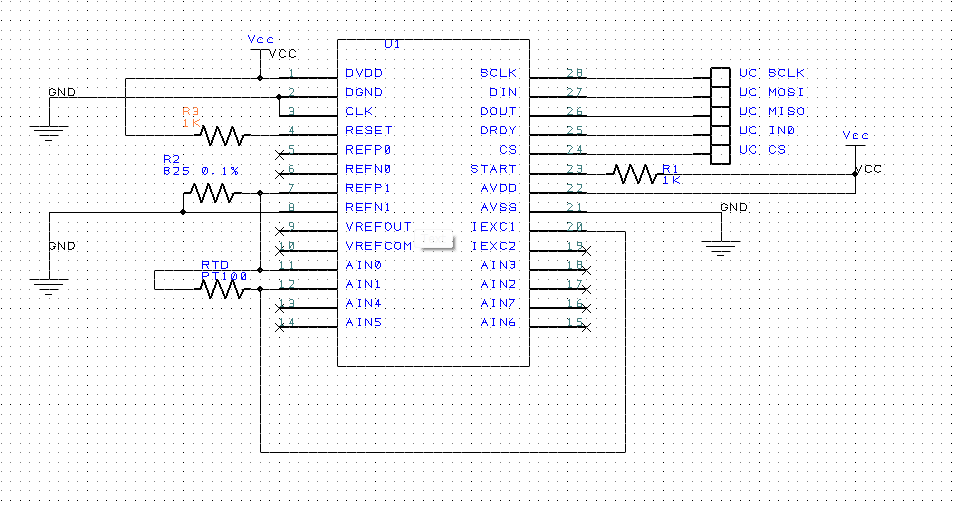
I am trying to get an ADS1248 to talk SPI to a Piccolo to read a 4 wire RTD.  I have the SPI communicating and I am able to setup the control registers but I am having a problem with getting a stable reference input.  I have it wired the same as the example in the app note http://www.ti.com/lit/an/sbaa180/sbaa180.pdf?DCMP=hpa_contriubted_article&HQS=sbaa180-ca.  I have the ADS1248 configures to output 1 mA on IEXC 1 and 2 and use REF0 as reference.  Internal reference is on to activate IDAC current.

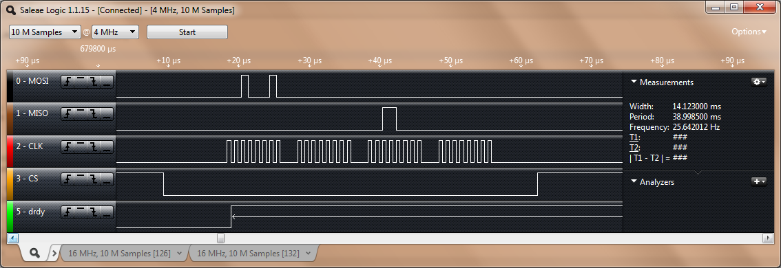
Before connecting anything to REF0N and REF0P I already have a voltage differential on the reference while CS is high (3.3V).  This voltage differential drops to 0 when CS goes low.  When I connect the bias resistor and rtd as the app note shows, I get an offset to the reference with a dip in it when CS goes low.  This also seems to have an effect on the excitation current after a period of time, the current drops over time for some reason.  Eventually this current will drop to zero and the ADS1248 will stop responding to all commands.

  • Hi Andrew,

    Welcome to the forum!  Please send us your specific schematic with all values used and all register settings.

    Best regards,

    Bob B

  • MUX0 = 0x00

    MUX1 = 0b00101000 for internal ref on and ref1 selected

    IDAC0 = 0x06 for 1000 uA

    IDAC1 = 0x89 for IEXT1 and IEXT2 current source.

  • Hi Andrew,

    I'm a little confused from your previous discussion relative to the schematic. Make sure you are correctly measuring the REF1 connections and not REF0 as you originally stated. 

    If you want 1mA of IDAC current then I would turn off the second source that is unconnected.  In this case IDAC1 register should be 0x80.  If you want 2mA of current, then you should set IDAC1 to 0x88 where both current sources are fed through a single pin.

    For stability, VREFOUT requires a capacitor.  At least 1uF should be connected between VREFOUT and VREFCOM. VREFCOM should also connect to GND.  This is discussed on page 29 of the datasheet under the section Internal Voltage Reference.

    What voltage is VCC?

    Best regards,

    Bob B

  • I have had it connected to both REF0 and REF1, both work the same.  The MUX1 register was set correctly for the setup.  VCC is 3.3V.  I have it connected to a Piccolo eval board which is providing the 3.3.

    I have been setting both current sources just for reference.  I have another 825 ohm resistor across the second one so I can measure the voltage to make sure it is still outputting current.  Something happens in the ADS1248 where it goes into shutdown state and the only way I can tell is to monitor the voltage across the resistor.

    Do I need a cap across Vrefout if I am not using it?  I have tried adding one and it did not change anything.  I am really confused why REF0 and REF1 are providing a voltage level out causing the reference to change.

  • Hi Andrew,

    If you use the internal reference (which is required when using the IDACs) then you must have a capacitor at VREFOUT.  You should be able to measure 2.048V at VREFOUT with respect to ground.

    How are you connecting things together?  Are you using a protoboard?  How effective is your ground?  Have you checked to see if VCC drops in voltage when the IDACs are turned on?  Any chance you can post a picture of your test setup?

    Initially I would try and keep things really simple.  For example connect IEXC1 (pin 20) directly to the resistor connecting the other end of the resistor to ground.  You should see 825mV across the resistor when the IDAC is turned on for 1mA.  I would not worry about the reference until you discover the cause of the problem with the IDAC.

    Best regards,

    Bob B 

  • I have it on a prototype board with a DIP adapter.  I have verified the current source is working with the method that you have described, I connected the resistor from the source to ground and it measures 825 mV on the scope.  I have also verified the vref voltage is about 2V.  If I connect ref0n to gnd and measure across ref0p to ref0n I measure 1.7V.  Nothing else is connected to ref0.  Ref1 does not appear to have any voltage on it, but once I connect it to the RTD and resistor the signal will start to fluctuate.  The reference fluctuates more than the signal from the RTD.

  • Verified that 3.3 is constant when the current is enabled.

    This morning I changed the reference to be the internal reference, which is measuring 1.97V.  Moved Rbias off of Ref1 and placed it on an open area of the prototype boad.  Now the RTD is not connected to the reference and I am simply using the internal reference, so I am loosing some accuracy.  The voltage across Rbias is now staying constant and at the correct level and reading the differential voltage on the input is more stable.  I only have a problem when I connect to REF0 or REF1, this causes my reference to be unstable because the Reference points have a voltage level on them.

  • Hi Andrew,

    There could be a problem when using the REF0 input as there is the potential that there was a writing error to the MUX1 register and the REFSELT bits are set to 11.  This sets the internal reference to the REF0 pair which would conflict with the external reference connection.  This should not happen on the REF1 input pair, so I'm not sure what can be causing the problem at REF1.  One thing for now is to only connect to the REF1 pair until we figure out what is going on.

    Can you send me a screen shot of the communication?  In particular I would like to see the read back of the MUX1 register.  One thing that can disrupt communication is the automatic posting of results when reading/writing registers.  I always issue the SDATAC command to prevent any corrupted communication prior to changing the register settings.

    Best regards,

    Bob B

  • Here are the signals for reading MUX1.  I had issued a 0x16 command to stop the continuous read.

    REF1 has the same problem.  When I connect Rbias across REF1 the voltage across the resistor drops 100mV, from 825 to 725 mV. 

  • Andrew,

    I'm not sure why you are sending the extra clocks at the end, but the read back of the MUX1 register appears correct.

    When you see the 100mV shift, is the RTD connected?  That would make sense.  Is the REF1 reference still drifting?

    Best regards,

    Bob B

  • If I have the RTD circuit with the current reference feeding the rtd which then goes through the 825 Ohm Rbias resistor then to ground everything looks right.  I get 825mV across Rbias and the RTD voltage will change with temperature.  If I then connect Rbias, to REF1 it drops 100 mV.  I would expect that the reference input would not change the voltage across Rbias.  Should connecting the reference input effect the voltage across Rbias?

    It is also not always 100 mV, just tried it again and it is a little higher, almost 250 mV.

    As for stability, the voltage across Rbias is stable until I connect it to REF1.  VREF is stable, although it is a little low t 1.96V.

  • Hi Andrew,

    The reference inputs are high impedance inputs, so you should not see any loading.  There should not be a voltage drop when you connect them.  Part of the excerise of going through the other steps was to isolate the problem.  As the problem appears to be directly related to the reference inputs, all I can think of that could have happened is at some point the reference inputs became damaged.  If the ESD cells conducted due to an accidental excessive current flowing through them from exceeding one of the Absolute Maximum Ratings specifications (listed on page 2 of the datasheet) then there may be some sort of short in the ESD cell.

    At this point I would suggest replacing the ADS1248 with a new one.

    Best regards,

    Bob B

  • I have two ADS1248s on dip adapter boards.  I swapped to the second one and it worked yesterday.  I left it on last night and now it is doing the same thing.  VREF is wandering up and down, from 1.4 to 2.06 V, and REF0 is slowly wandering.

  • Hi Andrew,

    I'm sorry to hear that you are still having issues.  The fact that the replacement device initially worked and failed over time is probably due to issues with the prototyping system.  Unfortunately the ADS1248 is quite delicate with respect to ground.  Protoboards are notorius for oscillation and noise pickup.  It is not hard to exceed one of the Absolute Maximum Ratings.

    When prototyping a system prior to constructing a PCB board it is better to use a proto board where components can be soldered and wired connections are also soldered and wired with short connections.  The traditional white plug in breadboard has lots of inductance and capacitance.  It is possible to use, but most people (including myself) are in too much of a hurry to wire the board correctly.  What I'm referring to here is trimming all wires to the correct lengths and making sure that they do not cross over one another.  All components used should also be trimmed to length, especially capacitors.  Using component leads for connection to power supplies, scope probes, volt meters, etc. is not a good idea.

    If you have loops of wires and components with long leads, don't expect to get good performance from a 24-bit device.  If nothing more, the noise will be too high to get any type of decent performance.

    Best regards,

    Bob B

  • Built a new prototype on a SchmartBoard.  Has the same problem.  When I first turn it on I have 1.76V across Rbias, should be 825mV.  It works for a while, then goes unstable.

  • Hi Andrew,

    I'm sorry that you are still having issues.  This is a primary application for this device so it should work.  Can you send me some pictures of your prototype setup?  Maybe I can help diagnose the problem.

    Best regards,

    Bob B