This thread has been locked.

If you have a related question, please click the "Ask a related question" button in the top right corner. The newly created question will be automatically linked to this question.

ADS1247's result is unstable!

Other Parts Discussed in Thread: ADS1247

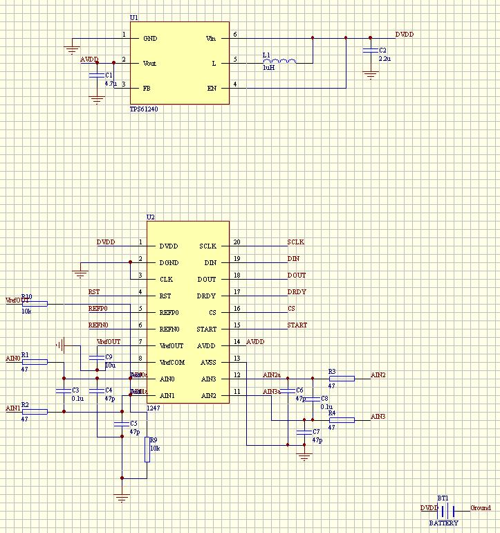
I have connect the ads1247 as the following picture.

The AIN0 and AIN1 node is connected,but when I read the result.8 bit of the result is unstable.

Result:000022 000015 FFFFFD 00004B 00002F 00004A 00006C 00000B 00002B 00004B  000061 000037 000008 00000D 000012 FFFFF9 FFFFF7 00001F 000038 FFFFFE 000053 00004E 000032 000030 00003B 00001B 000059 00001B 000027 00002A 00003B.

And I have connect the AIN0 and AIN1 to standard signal generation,the result is almost correct.But  8 bit of result is unstable too.By the way,I use the internal reference voltage of ADS1247.

void TI_CC_RDATAC(void)
{
    // Set SSN to active low
    P0_4 = 0;
    while(P1_4); //wait for the ADS1247 ready signal
    U0DBUF = 0x12;
    while(!(U0CSR & U0CSR_TX_BYTE));

        // Clear transmit byte status
     U0CSR &= ~U0CSR_TX_BYTE;
      int i;
    for (i = 0; i< 3; i++)
    {
        // Write dummy byte to USART0 buffer (transmit data)
        U0DBUF = dummyByte;

        // Check if byte is transmitted (and a byte is recieved)
        while(!(U0CSR & U0CSR_TX_BYTE)) { asm("NOP");}

         // Clear transmit byte status
        U0CSR &= ~U0CSR_TX_BYTE;

        // Write received byte to buffer
        data[i] = U0DBUF;

    }
}


Somebody can help me?

Thanks! 

  • What data rate and PGA gain are you using? This may be normal performance depending upon these conditions - you have a 118 code variation peak-to-peak, which is an ENOB of 19.03 bits. Check the datasheet and compare the noise listed under your data rate and PGA conditions and see if this ENOB is out of line. If it is, then we need to investigate where the excess noise is coming from.

  • data rate:5 sps,PGA:1.I have checked the datasheet,ENOB should be 21.5(19.1).

  • While the noise larger than you expect, there are a few things that you can look at to lower the noise.

    The first thing I noticed is that you use a boost converter for the supply. Since most of these DC/DC converters are noisy and can create spikes on the supplies, you want to be careful using them. If you can, replace the boost converter with a 5V supply that has low noise. Then repeat the measurement and check to see if the noise level drops. This could be a larger contributor to the noise.

    Also, the layout of the schematic may contribute to the noise problem. Input traces should be as short as possible, while the input capacitors should be as close as possible to the input pins of the ADC. The inputs should be shorted near the input pins so that the extra trace should not pick up any stray EMI. It would be best to have a continuous ground plane under the device and make sure that the digital lines do not cross under or couple into either the reference  or the inputs.

    The reference should also be a clean, low noise reference. However, this is likely to give you more noise when you have a larger input signal, and less when your input is small or near zero. Of course that would depend on the type of noise you have in the reference. What type of reference are you using?

    It might help to have a clearer idea of your application and the circuit you are using. If you have extra information such as a full schematic or a layout, let me know and I will email you directly.

    Joseph Wu

  • Thanks for your help! I have used a 5V battery instead of  DC/DC converters.The variation of result become smaller significantly.By the way,I use a internal reference of ADS1247.The internal reference voltage  is 2.048V.

    I want to ADS1247 to measure strain gauge,the signal is quite small.The full scale is only 0.5mV/V.

    I upload the a full schematic and a layout tomorrow.