This thread has been locked.

If you have a related question, please click the "Ask a related question" button in the top right corner. The newly created question will be automatically linked to this question.

ADS1258 - Random errors

Other Parts Discussed in Thread: ADS1258

HI all,

I have an acquisition system based on ADS1258, utilizing 8 of its channels in the single ended mode. The problem I am facing is i am getting a constant error value every other time, say for example, I finish reading all 8 channels the first time, it is all comming correctly, the second round of reading returns a constant error value (different for individual channels) and this loops. Here is how I am initializing the register

CONFIG0  = Fixed channel mode | SPI_RST 256
CONFIG1  = Idle mode sleep | Delay (0) | Data rate (2)
GPIOC       = 0x00
GPIOD       = 0xFF
MUXDIF     = 0x00
MUXSCH   = 0x00
MUXSG0    = 0xFF
MUXSG1    = 0x00
SYSRED    = 0x00

My SPI runs at 4.5MHz and seems to be running ok as seen in the waveforms acquired from my oscilloscope.

CH1: DRDY

CH2: SPICLK

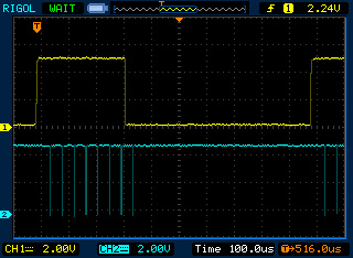
CH1: START (conversion)

CH2: DRDY

My code goes like this. A timer is set to be triggered every 1mS at which the ISR raises the START conversion line. I then receive conversion completion through EXTI interrupts since the DRDY lines are connected to my controller so as to generate EXTI interrupt. After receiving the 7th sample in a batch I lower the START conversion line. After receiving the 8th sample I send the whole batch to my PC through USB. A new cycle starts when the timer is triggered after 1mS. Now what are the odds that I receive a constant error value for all channels in every other batch? I walked through my code for blunders but it is quite simple to make any (I mean I didn't find any!). Since I am reading in channel data read direct mode, I have made sure that enough time elapses between two channel read operations.

  • MM,

    I apologize for the delayed response. Your problem sounds like it is in your SPI communication timing.

    What are you running your master clock at?

    Note that there is one data register in the device. As a conversion completes, DRDY goes low and the result of the conversion is placed in the data register. If you're monitoring DRDY, then you clock the data out before the next conversion is complete. Since you're sharing the SPI bus, you would be using the Channel Data (register format) read - which requires 40 SCLK cycles. Now if you are using a data rate of 125kSPS, then the SCLK would need to be greater than 5MHz. This is shown below

    With new conversion data coming every 1/125k = 8us, you have a clock period of 8us/40 = 200ns, which is a clock rate of 5MHz.

    Increasing your SPI speed may be a fix to your problem.

    Regards,

    Tony Calabria

  • Hi Tony,

    My SPI SCLK is running at 4.5MHz. I am sampling 8 channels every 1 mS, so that would make 8ksps i guess. More over the trace I collected by probing the DRDY and SCLK lines using the oscilloscope (as shown in my original post) the entire (3 bytes of) ADC data is collected well before the DRDY line is asserted again. In short there will be 8 back to back conversions ever 1 mS, yet the oscilloscope trace confirms that data is read in before it gets overwritten by the next conversion result.

  • Your master clock (fclk). Are you using the internal 15.729 MHz clock, or an external clock of some frequency?

    Also, what are you setting your DRATE[1:0] bits to. Your first post says Drate (2). I just want to verify that you are writing DRATE[1:0] = 10 in the CONFIG1 register. The combination of your master clock (fclk) frequency and the DRATE[1:0] bits in your CONFIG1 register set your data rate (see page 37 of the data sheet).

    Can I get a scope shot of your /CS, SCLK, and DOUT signals to verify that you are reading on the correct edge of SCLK.


    Regards,

    Tony