This thread has been locked.

If you have a related question, please click the "Ask a related question" button in the top right corner. The newly created question will be automatically linked to this question.

ADS1115 not finishing conversion

Other Parts Discussed in Thread: ADS1115, ADS1113, BQ77908A

Hi!

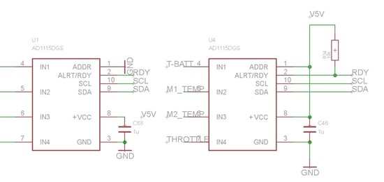
I have a board with 2 ADS1115 with addresses 0b1001000 and 0b1001001

intended for 4ch single ended measurements. I2C speed is set to 100k.

I want to use them in single shot mode but it seems that they never finish

a conversion. Chip markings are: 11 BOG1

I have stripped my code (using codevision) down to:

   #define ADC_1          0b1001000
   #define ADC_2          0b1001001
   #define CONFIG        0b00000001
   #define RESULT        0b00000000
   #define COMPLETE  0b10000000

   conf = 0b1100000111100011;

   twi_tx[0]= CONFIG;
   twi_tx[1]= conf>>8;
   twi_tx[2]= conf;

   twi_master_trans(ADC_2, twi_tx, 3, twi_rx, 0);
        
   delay_ms(2);

   twi_tx[0]=RESULT;
   twi_rx[0]=0;
   twi_rx[1]=0;
   twi_master_trans(ADC_2, twi_tx, 1, twi_rx, 2);
   result= ((unsigned int)twi_rx[0]<<8)|twi_rx[1];

and running it gives only 0x8000

When I had:

         while (!( status & COMPLETE))
            {
                twi_tx[0]=CONFIG;
                twi_rx[0]=0;
                twi_rx[1]=0;
                twi_master_trans(addr, twi_tx, 1, twi_rx, 2);
                status=twi_rx[0];
                delay_us(100);
            }

instead of 2ms delay then it never get past that loop.

I have played with the channels, sampling rate, comparator bits for no avail.

I have run out of ideas what else to check....

For me it seems that the ADS1115 chips have been damaged, but what makes it dubious

is that the I2C communication works correctly and that there are two chips in the system.

What could be the issue?

  • Hi Marek,

    I'm a little confused by the timing as I don't know why you are sending the extra byte in the configuration write sequence, and the read conversion result sequence shows a NACK.  So it doesn't seem like the code follows the logic analyzer timing and the result is inconclusive.

    What do you have connected to the inputs?  If the result is negative full-scale, that would mean that something is not configured correctly, or you have the inputs connected incorrectly.  Can you show me your schematic?

    One thing you can try is write a configuration and then read it back to make sure you are writing/reading correctly.  You may think that you are communicating correctly, but if you see a NACK in the 9th clock, then you are not.

    Best regards,

    Bob B

  • Hi Bob, thanks for answering!

    Yes, sending 3 bytes was a mistake. When I stripped the code then I removed the configuration of the threshold registers and specified the wrong number of bytes to send,

    but that alone is not a big mistake in a sense that it shouldn't affect the acquisition and the result in the conversion register.

    I corrected that and nothing changed.

    I also tried to read more then 2 bytes from ADS1115 - in that case the first three gave ACK and the fourth NACK

    I am using both of these devices in the 4ch single ended mode. There's not much to see in schematic..

    I investigated the situation a bit more deeply.

    For debugging configuration I use  0b1100001111100011;

    (starting from msb)

    b15:1     Begin single conversion.

    100 Channel 0 in single channel mode

    001 +-4V range

    1    Single shot mode

    111 860SPS data rate

    0    Trad. comparator

    0    Active low com polarity

    0    Non latching comparator

    11  Disable comparator

    At CH0 I have voltage divider giving me a range from 0 to +2,7V

    From 0 to ca 2V the output code is  x8000. This "blind zone" made me think that

    the conversion result is always the same. In fact, it is not.

    2.1V - x8260 or x8270 (just these two values like the resolution would be 10 in HEX)

    2.3V - x88b0/x88a0

    2.5V - x9c30/x9c40

    2.7V - xa990

    4.056V- xffb0

    At the same time the voltages at the other inputs are:

    CH1 = 4.056V

    CH2 = 4.056V

    CH3 = 0V

    Now this would be logical if it would be in differential mode but I clearly configured it 

    to single channel operation...

    Nothing seems to get rid of the NACK at the end of the data receive.

  • Status update. Converters are working in differential mode, using configuration

    described in previous messages I now tried to change the voltage on CH1 and the

    code supposing to measure CH0 changes when I change either of the inputs.

    How is this possible using the 0b1100001111100011; configuration word?

    How would it be possible to verify that it actually is ads1115 and not ads1113 for an instance?

    Chip marking seems to be correct - BOGI

    Now when I read back the contents of the conf register right after writing xC3E3 to it

    I receive x42E3, so the device has changed its operation mode from single shot to continuous

    plus cleared the conversion ready flag.

  • Hi Marek,

    I'm sorry to hear you are still having issues.  It would seem to me that there are communication problems.  When reading from the ADS1115 and you get a NACK from the controller, then you need to investigate why this is the case.

    What value of resistor are you using for I2C pull-ups for SDA and SCL?  Do you have anything else connected to the I2C line besides the micro and the two ADS1115s?  Instead of using a logic analyizer, you might try connecting a two channel oscilloscope to the I2C communication lines to view the actual transition periods.  Sometimes there is extra capacitance on the lines which cause transmission issues.  How do you have your system connected?  Proto breadboards often have issues with adding capacitance.

    Best regards,

    Bob B

  • Hi Bob,

    I will take the look with oscilloscope tomorrow, but last time I checked,
    the signals were looking good. I have relatively small PCB and the
    pullups are 4.7kΩ. Only other device beside the two ASD1115 on the
    bus is BQ77908a which communicates correctly.

    Regards,

    Marek

  • Hi Marek,

    4.7k should be fine, but you could try 2.7k to see if that makes a difference.  If you send me pictures of the layout I can check through it to look for any possible issues.  You might also check to see if you have any cold solder connections or unclean areas with flux residue around the ADS1115.

    Best regards,

    Bob B

  • Hi Bob,

    seems that I have created additional confusion to this mess that I'm having.

    I had misconfigured the I2C transactions so that the higher byte in the configuration

    register was rewritten and from there came the change from single shot to continuous mode.

    But again, this mistake was due trying to quickly hack through the problems I'm having with the ADC's

    and the problem still persists.

    For some reason the conversion ready bit (MSb) in the config register is not altered after 2.5ms

    when running in 860SPS.

    Also the device IS in the differential mode, changing the value at either CH0 or CH1 alters the

    output value....

    Anyways, my conclusion is that either the input mux.es are damaged or TI had wrong label on the chip.

    I just received new converters, soldered them on board and everything works as it should now....

    Regards,

    Marek

  • Hi Marek,

    I'm glad you are making progress.  However, I believe you are still having communication issues, or a connection issue.  The ADS1115 always measures differentially, but when selected so that AIN- is at ground only the selected input should matter. The other inputs should not be affecting the result.

    The conversion ready bit is only useful for single-shot mode.  If you were in continuous mode (by accident), it is doubtful that you will ever see a time when not converting.

    Best regards,

    Bob B

  • Hi Ben,

    since I managed to write the configuration register of ADS and read the same values back

    from it then I assume that the communication between the ADS and uC should have

    been correct. The signal I saw on the scope was a bit noisy but the translated values

    were always correct (reading both with uC and scope) I can post the images tomorrow.

    Also, since after changing the ADS chips all those troubles I was experiencing went away

    without changing a line of code then it must have been the ADS chips that were to blame...

    Regards,

    Marek