This thread has been locked.

If you have a related question, please click the "Ask a related question" button in the top right corner. The newly created question will be automatically linked to this question.

AFE4300EVM-PDK Evaulation Board

Other Parts Discussed in Thread: TUSB3410, AFE4300, CC2541, MSP430F5528, AFE4300EVM-PDK

TI supplies an Evaluation Module to test out the AFE4300 chip with some LabVIEW interface software (TUSB3410).  From the documentation the software comes as an installer which installs an executable onto the PC, but is it possible to get the actual source code so we can do further development work.

Chris

  • Chris,

    Unfortunately we are not able to release our Labview source code for our GUIs.

  • Hi Amy,
    Damn! that's a shame it could have really reduced our development time .  Does TI have any LabVIEW code on this IC that it can share publicly?

    Thanks Chris

  • Chris,

    Can you give us some background on your company, what you're trying to do, etc.?

  • Sure no problems Amy.

    We are a design team at  Royal Perth Hospital (a major tertiary teaching hospital in the State of Western Australia) and have been asked by a team of plastic surgeons (across several other tertiary hospitals in the state) to develop a bio-impedance measuring device for use in monitoring the health of muscle flap transplants over several days.  It is hoped this will provide a continuous real-time signal that will be processed to provide a simple user GUI for Nurses to determine if the transplant is failing or has problems.

    We are planning to use the TI AFE4300 in combination with the MSP430F5528 and CC2541 communicating to a laptop running our custom LabVIEW application.

    Chris

  • Chris,

    Our labview GUI is intended to only be used with our evaluation module and only for validation purposes. So, with that said, unfortunately we cannot release the source code.

  • Hello,

    We have purchased the AFE4300EVM-PDK Evaluation Board at Royal Perth Hospital but we are coming across several issues:

    1. At simulation switch 3 of SW3 is switched on for a 1k Ohm resistor simulation. IOUT & VSENS terminals are also connected across with each other for the simulation test as described by the AFE4300 Development Guide (pg 29). On the front panel under Device Configuration - 'BCM Control', VSENS1 & VSENS0 are set to + and - dials respectively. & IOUT 0 and IOUT1 are also connected to FB0 & FB1 respectively. The Weight Scale Control tab was switched off. Then moving to "BCM Measurement" on the Front panel both "Known Resistor 1" and "Known Resistor 2" are calibrated to 1k ohm resistance before I pressed "Measure BCM". The calibrations were successfully done (as shown below) but at pressing measure BCM, an error saying "Empty the Weight Scale for Offset Measurement", even though the Weight Scale Control is switched off. The The AFE4300 Development Guide was followed word by word (pg 29) and an error still occurred.

    Could you please advise what should be done to approach this problem?

    Error Message at Pressing measure BCM:

    2. A resistor tree was set up on a breadboard was set up to test the AFE4300 out of simulation mode and the connections were done as done in simulation except across the resistors on the breadboard. The resistance was also made to be 1kOhm however in this case even the calibration was not successfully done. The message, "Empty the Weight Scale for Offset Measurement" also appeared. How do you suggest we approach this issue?

    3. Do you have any information about the MMB3 modular motherboard that comes with the AFE4300EVM-PDK?

  • 1 and 2. On the BCM Measurement Tab you should change the Meter Type to Hand to Hand. You might be using foot-foot by mistake. Also, when you calibrate do not select calibrate all since you are not calibrating everything. Only select the calibration you need. For more information on the BCM measurement Tab (which is not mentioned in our Development Guide) you should refer to our App not on Impedance Measurement. This is located on our product folder and I have also included the link below.

    http://www.ti.com/litv/pdf/sbaa202

    3. We only use this as a simple SPI interface, but if you would like to see more information on this board, the schematics are referenced in this e2e post.

    http://e2e.ti.com/support/data_converters/precision_data_converters/f/73/t/72288.aspx


  • Hi Amy, Thank you for all your help.

    We just have a few more quiries with regard to the calibration of the device:

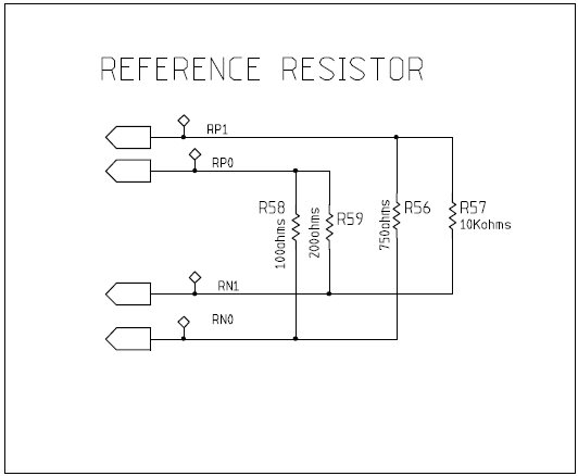
    1. With Calibration of FWR Mode is appears that the reference resistors run through RP1 and RN1 through the resistor R57 which is labelled in the AFE4300 User Development Guide as 10KOhms. The "Impedance Measurement with the AFE4300" document on page 6 shows that R57 is 950Ohms and also after measuring it the resistance was 950Ohms. Was the 10KOhm label a typo of some sort?

    2. Also when calibrating in IQ Mode, is appears to switch to another reference resistor path where the pointer switches to run through RP0 and RN0 (as displayed on the BCM Control - Device Configuration of the Front panel) where the resistor in between is R58 at 100Ohms. We measured the resistance across this as well to get 99.2 Ohms. This appears to be much more reasonable than that across R57. Does IQ mode use more than one reference resistor in this process? e.g. run through RP1& RN1 then switch to RP0 & RN0?

    3. Also in the front panel the labels "Known Resistance 1" and "Known Resistance 2" refer to R57 & R58 in this case?

  • Essentially, we would like to use IQ mode to measure one frequency instead of four. We would like to view both magnitude and phase outputs which is why we want to use IQ mode. How can this be done?

  • 1. 10kOhms is the actual value of the resistor that is placed in that position. The 950Ohms is the effective resistance in that position since there are other resistances in the circuit that effect it.

    2. We do a reference resistor measurement to calculate the phase.. Ideally this would be 0, but the phase of the actual resistor minus phase of reference resistor will be the effective calculated phase.

    3. Correct

    The GUI we provide automatically does four frequencies. This can be done if you are doing it manually though. However, I'm assuming you are using our EVM GUI.

  • Thank you for your response.

    We have emailed texas instruments with some questions including those ones but they have not been able to answer them and asked us to post them to the forum. So we have a few more questions:

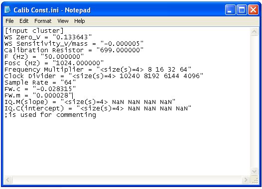
    1. What is the function of the frequency multiple in the calibration constant in file as indication by the "Impedance Measurement with the AFE4300" document.

    2. The calibration constant file has a section "F(Hz) = 50 Hz". What does that represent? Is it not the same as our decimation filter options under ADC control (on the front panel of the software)?

    3. Is the DDS block in BCM control (software front panel) internally rounded off to the nearest value of the desired frequency instead of what is typed in?

    4. As answered by your collegue If only one reference resistor is used for the calibration in IQ mode then what is the purpose of R56 and R59? There is no option of connecting RP0 to RN1 and RP1 to RN0 as shown in the circuit diagram below. And also, R59 has the highest resistance accuracy (0.1% as opposed to 1%) compared to the other reference resistors.


  • Mais,

    1. It is for the IQ mode. More information on IQ and FWR can be found in our datasheet. Also to know the difference between Multi Frequency bio-impedance analysis and single frequency, you can read section 1.1 on page 2 of the "Impedance Measurement with the AFE4300" document

    2. It is the FWR frequency. It is not used when in IQ mode.

    3. When in FWR mode, the frequncy is rounded to the nearest kHz. When in IQ mode you have have a menu of specific options you can choose from.

    4. You can choose 2 out of the 4 possible resistors for calibration. For R59, that was the accuaccy available for the choosen resistor value. Ideally they would all be 0.1% accurate, because it is better to have the highest accuracy possible.

  • Hi,

    i have question about 1):

    so basically, multi frequency BIA is just SOME single frequency BIA in FWR mode at SOME different frequencies?

    Thanks

    Zo

  • Zo,

    Yes your understanding is correct.


    Regards

    Praveen