This thread has been locked.

If you have a related question, please click the "Ask a related question" button in the top right corner. The newly created question will be automatically linked to this question.

ADS1255 Timing, Sequencing, Set up issue.

Other Parts Discussed in Thread: ADS1255, ADS1256

I'm attempting to use the ADS1255 but I'm running into some issues. First and foremost the ADS1255 seems to be resetting randomly during testing. The configuration I set eventually gets wiped somehow. The following is the initialization function for the ADS1255:

ADS1255CSlow();

    while(!SPILock(spiInitData.channel))
    ;

    SPIPut(ADS1255_SPI_CHANNEL,0x0F);   // Turn off read continuous mode
    SPIGet(ADS1255_SPI_CHANNEL);
    DelayMs(1);

    SPIPut(ADS1255_SPI_CHANNEL,0xFE);   // Reset ADS1255 to defaults
    SPIGet(ADS1255_SPI_CHANNEL);
    DelayMs(1);

    SPIPut(ADS1255_SPI_CHANNEL,0x53);   // Write to reg 0x03
    SPIGet(ADS1255_SPI_CHANNEL);
    SPIPut(ADS1255_SPI_CHANNEL,0x00);   // n-1 registers to be written
    SPIGet(ADS1255_SPI_CHANNEL);
    SPIPut(ADS1255_SPI_CHANNEL,0xA1);   // Value to write to register (1000 SPS)
    SPIGet(ADS1255_SPI_CHANNEL);
    DelayMs(1);

    SPIPut(ADS1255_SPI_CHANNEL,0x51);   // Write to reg 0x01
    SPIGet(ADS1255_SPI_CHANNEL);
    SPIPut(ADS1255_SPI_CHANNEL,0x00);   // n-1 registers to be written
    SPIGet(ADS1255_SPI_CHANNEL);
    SPIPut(ADS1255_SPI_CHANNEL,0x00);   // Value to write to register
    SPIGet(ADS1255_SPI_CHANNEL);
    DelayMs(1);

    SPIPut(ADS1255_SPI_CHANNEL,0xFC);   // Sync A/D conversion
    SPIGet(ADS1255_SPI_CHANNEL);
    DelayMs(1);

    SPIPut(ADS1255_SPI_CHANNEL,0xF0);   // Self calibrate command
    SPIGet(ADS1255_SPI_CHANNEL);
    DelayMs(1);
    
    SPIPut(ADS1255_SPI_CHANNEL,0xFD);   // Put ADS1255 into Standby mode
    SPIGet(ADS1255_SPI_CHANNEL);
    DelayMs(1);

    SPIUnLock(spiInitData.channel);
    ADS1255CShigh();

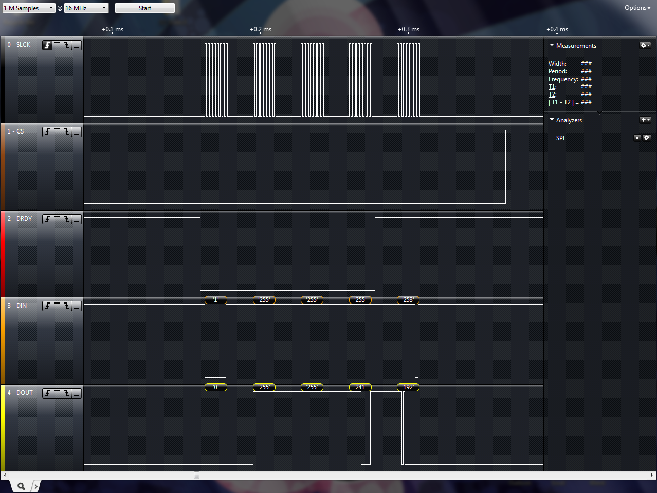
Initially the waveform looks correct as would be expected but the data received is completely wrong. The first     image is what the waveform looks like initially. 

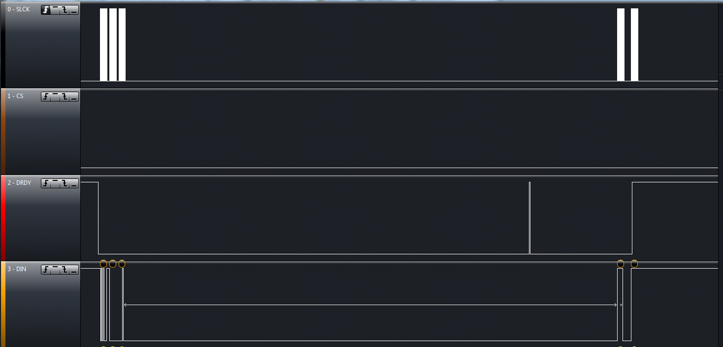
Then all of a sudden the ADS1255 will reset and start producing the correct data but the waveform looks wrong. The second image is what the waveform looks like when the ADS1255 resets. Notice the DRDY line is toggling when it shouldn't be but the data coming back seems correct.

My question is: A) why is the device resetting on its own
                           B) why does the correct waveform produce wrong data but the bad waveform produces correct data.

Thanks in advance 

  • Hi Austin,

    Welcome to the TI E2E Forums!

    Thanks for sharing you code! I see a few issues that could be causing your problem:

    • There's no WAKEUP command. WAKEUP should follow the SYNC command to begin conversions.
    • The self-calibration is getting interrupted. Table 21 in the ADS1255 datasheet indicates that self-calibration takes 3.6 ms. Your code only provides a 1 ms delay. Interrupting this process could be putting the ADS1255 into an unknown mode.
    • For the images, it looks like only one byte of data is read between /DRDY pulses. You need to read 3 data bytes as shown in figure 30, before /DRDY pulses, otherwise your data is corrupted. The fact that /DRDY is pulsing tells me that the complete data read-back in not happening. This is mentioned at the top of page 27 in the data sheet.

    Additionally, I have found that starting a conversion and then immediately putting the ADS1255 into standby before a conversion finishes can put the finite state machine of the ADS1255 into an odd mode. I recommend monitoring /DRDY in the code and delaying the standby command to allow at least 1 conversion to complete.

    Please let me know if fixing these issues removes the odd reset behavior and invalid data.

    Best Regards,
    Chris

  • IDK why everything looks messed up from what I sent but the code I posted is just the initialize function, its only called on system start up. It looks like only one of the images loaded correctly so let me try again. This is how the waveform looks after i call my initialization routine:

    Does this look correct?

    And after a minute or two (random amount of time), the waveform changes to this:

    This second image indicates that the ADS1255 is being reset during runtime based upon the way the DRDY timing.

    The first image is what I expect the waveform to look like but provides invalid data, while the second looks wrong but provides somewhat expected data...

    --------------------------------------------------------------------------------------------

    I have adjusted the delay after the self cal to wait 5ms before continuing and the wakeup command is handled during reading which the code was not posted for.

  • Hi Austin,

    Don't worry about the code posting. Our forum is trying to autolink the "ADS1256" text to the ADS1256 product page and it looks like some of the HTML code is getting inserted. I've put in a request to IT to fix that.

    I see the 1st image now. It looks fine!

    Would you be able to save you're complete logic analyzer data and send me the file to look at? I have the Saleae logic analyzer too!

    Best Regards,
    Chris

  • 0358.Logic.zip

    This is what the current waveform looks like. I notice there is a huge gap between the MID byte and the LSB read request but there is no delay there. the current Read loop is here:

        ADS1255CSlow();
        while(!SPILock(spiInitData.channel));
        
        SPIPut(ADS1255_SPI_CHANNEL, ADS1255_DUMMY_WRITE);   // Wake up ADS1255
        Delay10us(1);
        SPIGet(ADS1255_SPI_CHANNEL);
    
        while(ADS1255_DRDY);
    
        SPIPut(ADS1255_SPI_CHANNEL, ADS1255_RDATA);   // Read analog input from ADS1255
        Delay10us(1);
        SPIGet(ADS1255_SPI_CHANNEL);
    
        SPIPut(ADS1255_SPI_CHANNEL, ADS1255_DUMMY_WRITE);
        Delay10us(1);
        data_ADC.lsb = SPIGet(ADS1255_SPI_CHANNEL);
    
        SPIPut(ADS1255_SPI_CHANNEL, ADS1255_DUMMY_WRITE);
        Delay10us(1);
        data_ADC.midb = SPIGet(ADS1255_SPI_CHANNEL);
    
        SPIPut(ADS1255_SPI_CHANNEL, ADS1255_DUMMY_WRITE);
        Delay10us(1);
        data_ADC.msb = SPIGet(ADS1255_SPI_CHANNEL);
    
        SPIPut(ADS1255_SPI_CHANNEL, ADS1255_STANDBY);   // Put ADS1255 into Standby mode
        Delay10us(1);
        SPIGet(ADS1255_SPI_CHANNEL);
        Delay10us(5);
    
        SPIUnLock(spiInitData.channel);
        ADS1255CShigh();
    
        return data_ADC.ADC_Value;
  • Hi Austin,

    Here are some of my observations from the logic capture:

    • I recommend sending the SDATAC command first thing to exit from the read data continuously mode. This mode is not being utilized in the code, because the RDATA command is being sent everytime you read data.

    • I see in the code that the MUX register is set over and over. This only needs to be set once, and you'll only need to update the MUX register again if you reset the device or want to read a different channel.

    • In this screen shot you configure the MUX register and then there is a long delay until the SYNC and WAKEUP commands. If you notice, /DRDY pulses which tells you the device is already converting. If you implement the SDATAC command first and then put the SYNC and WAKEUP commands right after writing to the MUX your code will be more efficient and you won't be stopping mid-conversion to restart the conversion.


    • I also see that STANDBY is being used frequently, but WAKEUP is sent just 100 ns following. For debugging, remove the standby command. After you get working results then you can go back and try to reduce power consumption. As it implemented, it will not provide much power savings. Refer to "One-Shots Conversions" and Figure 20 in the data sheet later for an example of how standby mode should be implemented.

    All the data appeared to be consistent for this logic capture file. I didn't see the issue that you showed above. That said, the first bullet point above needs to be implemented, but the other three I mentioned are mostly optimizations that I don't are the source of the problem.

    Best Regards,
    Chris

  • In the init function I turn off continuous mode as well as set some other registers. Is this a one time thing or do I need to do this every time I take a read?

    I write to the mux register every iteration because my function is set up to read both inputs depending on the scenario of my system. Also I put the ADS in standby when Im not taking readings from the ADS. It just happens that the case I sent you is updating the reading on the screen continuously.

    So in my read function after I set the mux I should use the SDATAC command then the SYNC command then the WAKEUP command? I'll give it a try and post the resulting waveform shortly.

    Thanks

    Austin

  • Hi Austin,

    If you already send SDATAC first thing, then you do not need to send it again unless you enter read data continuous mode by the RDATAC command.

    Also, if you don't make any changes to the MUX or PGA, then you don't need to restart conversions with SYNC and WAKEUP.

    Are you getting valid data now?


    Regards,
    Chris

  • I have everything working as it should now. The waveform is correct but im still running into the issue of the ADS1255 resetting. Took 25 minutes of working correctly and then just resets. below is the new code. I'm I doing something wrong?

    ADS1255CSlow();
        while(!SPILock(spiInitData.channel));
    
        SPIPut(ADS1255_SPI_CHANNEL, ADS1255_DUMMY_WRITE);   // Wake up ADS1255
        SPIGet(ADS1255_SPI_CHANNEL);
    
        while(ADS1255_DRDY);
        
        if(ch == BASE_CHANNEL_SEL)
        {
            SPIPut(ADS1255_SPI_CHANNEL, ADS1255_WRITE_REG | ADS1255_MUX);   // Write to reg 0x01
            SPIGet(ADS1255_SPI_CHANNEL);
            SPIPut(ADS1255_SPI_CHANNEL,0x00);   // n-1 registers to be written
            SPIGet(ADS1255_SPI_CHANNEL);
            SPIPut(ADS1255_SPI_CHANNEL, ADS1255_CHANNEL_0);   // Value to write to register
            SPIGet(ADS1255_SPI_CHANNEL);
        }
        else if(ch == ROD_CHANNEL_SEL)
        {
            SPIPut(ADS1255_SPI_CHANNEL, ADS1255_WRITE_REG | ADS1255_MUX);   // Write to reg 0x01
            SPIGet(ADS1255_SPI_CHANNEL);
            SPIPut(ADS1255_SPI_CHANNEL,0x00);   // n-1 registers to be written
            SPIGet(ADS1255_SPI_CHANNEL);
            SPIPut(ADS1255_SPI_CHANNEL,ADS1255_CHANNEL_1);   // Value to write to register
            SPIGet(ADS1255_SPI_CHANNEL);
        }
        else
            return 0;
    
        Delay10us(1);
    
        SPIPut(ADS1255_SPI_CHANNEL, ADS1255_SYNC);   // Sync A/D conversion
        SPIGet(ADS1255_SPI_CHANNEL);
    
        Delay10us(1);
        
        SPIPut(ADS1255_SPI_CHANNEL, ADS1255_DUMMY_WRITE);   // Wake up ADS1255
        SPIGet(ADS1255_SPI_CHANNEL);
    
        while(ADS1255_DRDY);
    
        SPIPut(ADS1255_SPI_CHANNEL, ADS1255_RDATA);   // Read analog input from ADS1255
        SPIGet(ADS1255_SPI_CHANNEL);
    
        Delay10us(1);
    
        SPIPut(ADS1255_SPI_CHANNEL, ADS1255_DUMMY_WRITE);
        data_ADC.lsb = SPIGet(ADS1255_SPI_CHANNEL);
    
        SPIPut(ADS1255_SPI_CHANNEL, ADS1255_DUMMY_WRITE);
        data_ADC.midb = SPIGet(ADS1255_SPI_CHANNEL);
    
        SPIPut(ADS1255_SPI_CHANNEL, ADS1255_DUMMY_WRITE);
        data_ADC.msb = SPIGet(ADS1255_SPI_CHANNEL);
    
        SPIPut(ADS1255_SPI_CHANNEL, ADS1255_STANDBY);   // Put ADS1255 into Standby mode
        SPIGet(ADS1255_SPI_CHANNEL);
        Delay10us(5);
    
        SPIUnLock(spiInitData.channel);
        ADS1255CShigh();
    
        return data_ADC.ADC_Value;

    Thanks,

    Austin

  • Hi Austin,

    Is "while(ADS1255_DRDY);" evaluating as "true" when /DRDY is HIGH or LOW? I'm assuming HIGH...

    I would have the read data code execute immediately following a /DRDY falling edge. Therefore, you should negate the second instance of "while(ADS1255_DRDY);" to "while(!ADS1255_DRDY);" so that you're reading data while /DRDY is low.

    Regards,
    Chris

  • That is correct the while loops are running while  /DRDY is HIGH.

    The sync command stops the operation of the ADS1255, Forcing /DRDY high until valid data is available. The second while loop is what waits for valid data. This means the read command wont happen till the falling edge of /DRDY.

    Attached is the waveform of the current setup posted before. As I mentioned everything looks good for a while then the chip seems to reset. look this waveform over and verify correctness please.

    3240.waveform.zip

  • Hi Austin,

    Something is going wrong with your communication after a period of time:

    Instead of sending 0x01 for read there is a byte with 0x81; also your write byte changes from 0x51 to 0x71 (or 0xD1 in other places)...

    Regards,
    Chris

  • Yes, this seems to be a SPI issue. I'll investigate into this further.

    Thanks